Table of Contents
surfaces
Configuration options
Areas can be documented using two different methods: after Gauss-Elling and based on Standard geometries (Triangles, trapezoids, etc.). The type of documentation Control line also uses standard geometries that are aligned with a defined straight line (see Documentation about building line).
If the scope of area objects should also be documented, then for the object type Route (see topic Courses) by deactivating the option Suppress route documentation for areas at the same time the scope can be created as route documentation.

In order to improve the clarity in the drawing, the documentation of the areas is based on the preset Layer Documentations_Flaechen stored (for 3D surfaces: Documentations_Flaechen_3D). This can be changed by selecting an existing layer in the drawing or by entering a new name using the keyboard. This layer is then used by DATAflor CAD created.
In addition, the Documentation simplified or the Number of points increased will. The discrepancy between the simplified documentation and the exact quantity of the selected drawing object will be in the range Documentation in the object manager or in the dialog Documentation (Im Info dialog > ![]() documentation) is displayed.
documentation) is displayed.
The decimal for the graphic documentation and for the entry of the quantity certificate in DATAflor BUSINESS or for export as a REB file can be changed. Possible specifications are: 2 or 3.
Various areas can be configured for the visible documentation in the drawing: Points, bending, Shapes and Standard geometries.
The options for Points and Shapes correspond to those for Courses.
Standard geometries
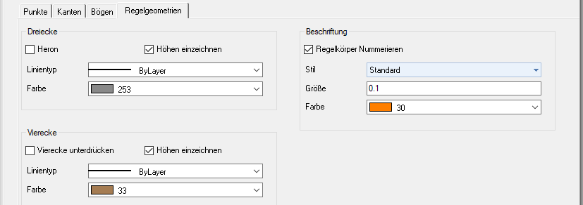
Here are the options Triangles heron and Suppress squares activate. You can find a further description of this in the chapter below Documentation method standard geometries.
With triangles and squares, the Line type and the Color can be set. Furthermore, the graphic representation of the Heights suppress.
For the numbering The font style and size as well as the color can be specified for the standard geometries.
bending
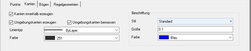
The option Dimension surrounding edges is essentially for documentation about Test edges or orthogonal necessary. This option can only be activated if the option Generate surrounding edge is activated.
Furthermore, the Line type, the Color and in the area Label the font style, color and size can be set.
Documentation methods
Two different documentation options are available for surfaces, whereby when breaking down into standard geometries (triangles, trapezoids, etc.), the triangles can optionally also be documented according to Heron. The different documentation methods not only affect the writing of the quantity statements, but also influence the drawing layout, which can be individually adapted.
Method 1: standard geometries
Areas are broken down into partial areas and listed individually in drawings and quantities. Different formulas are used depending on how the breakdown into standard geometries is carried out (see Explanation of calculation methods > Calculation formulas REB 23.003).
Triangles according to Heron: Optionally, the documentation of the triangles according to Heron can be activated during the breakdown into standard geometries. Formula 01 is used for triangles instead of Formula 03. Formula 01 derives the area using the base and the height, whereas formula 03 determines the areas using the base sides. Heron is always activated for 3D surfaces, as determining the surface with the height in 3D space can be problematic. The height does not provide any information about the position of the triangle in 3D space.
Suppress squares: Optionally, the documentation can be generated without rectangles when breaking it down into standard geometries.
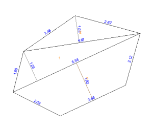
Area decomposition with standard geometries
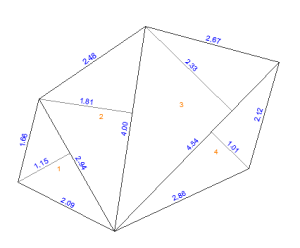
Area decomposition with regular geometries and triangles according to Heron
REB formulas used:
- 99 - Explanation of the object
- 01 - triangle (above base height)
- 04 - rectangle
- 05 - trapezoid
- 07 - district sector
- 09 - parabolic segment
- optional: 03 - standard geometry calculation with triangles according to Heron
Method 2: Gauss-Elling (not for 3D surfaces)
Values for formula 22 (irregular polygon from coordinates) are entered in the quantity statement (see Explanation of calculation methods > Calculation formulas REB 23.003). Will the Reference point changed, a different origin is selected for the calculation in the documentation (see Instructions for use > Documentation according to Gauß-Elling in the high coordinate range (Gauß-Krüger)).
This documentation method cannot be used for 3D surfaces, since according to REB specifications only 2 coordinates are possible, so the Z value cannot be taken into account.
REB formulas used:
- 99 - Explanation of the object
- 22 - Irregular polygon made of coordinates
- optional: 07 - additional circle sector calculation for circles
Automatic documentation
The procedure for creating documentation for surfaces is the same as for Courses.
The only specialty is the creation of Documentation variants when breaking down into standard geometries. In the case of surfaces, there are always several options for breaking them down into standard geometries (triangles, trapezoids, etc.).
Select variant
- If another variant is to be created, the object must be marked in the mass tree.
- Now you can use the right mouse button in the context menu Documentation the function Variant choose. You can find the function [Variant] also in dialogue Documentation (Im Info dialog >
 Documentary).
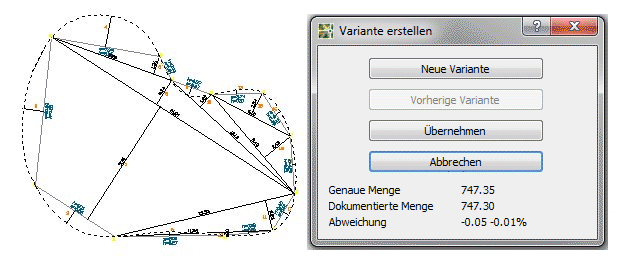
An [New variant] can be selected until the required documentation is displayed.
In addition to normal 2D and 3D surfaces, a triangulation be documented. For this, the triangulation must be recorded as a 3D object. The documentation of triangulations cannot be created or edited manually.
If documentation is created for an area, the route documentation is also created at the same time. This is necessary because there is a coupling to DATAflor BUSINESS the CAD objects and object properties can be transferred to positions. Exactly which property is used depends on the position in DATAflor BUSINESS dependent. The creation of route documentation for areas can, however, be suppressed (see topic Courses).
The manual creation of documentation or the editing of automatically created documentation is described under Edit documentation manually explained.
Documentation about test edges
The function [Test edges] offers the possibility of defining edges within an area to which the documentation is aligned. After defining the edges, the documentation is created automatically.
Application
- In the mass tree, mark the area whose content is to be documented.
- Now you can use the right mouse button in the context menu Documentation the function Test edges choose. You can find the function [Test edges] also in dialogue Documentation:
im Info dialog > documentary - Define the edge using two points.
To define the edge, select only points that are on the boundary. Use an object snap to do this.
- With the function [Drawing object] in the field of Derive you can use an existing straight line that has two intersections with the recorded area as a test edge.
- With the option [Individually] in area Delete can you single Test edges delete with the function [Everything] erase all edges.
- Close your editing with the function [The End] .
- The documentation is created in the drawing.
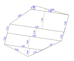
| without test edge | with test edge |
 |  |
For complete documentation, the values of the outer edges should be displayed. To do this, activate in the area bending the options Generate surrounding edges and Dimension surrounding edges.
Documentation about Orthogonal
The function [orthogonal] offers the possibility of defining edges within an area to which the documentation is aligned. For this purpose, vertical test edges are automatically created along a selected ordinate, on the basis of which the documentation is created.
Application
- In the mass tree, mark the area whose content is to be documented.
- Now you can use the right mouse button in the context menu Documentation the function orthogonal choose.
- Define the ordinate using two points. As soon as the second point has been defined, the edges are created.
- With the option Delete> [Single] you can delete individual edges with the function Delete> [All] erase all edges.
- Close your editing with the function [The End] .
- The documentation is created in the drawing.
| without orthogonal | with orthogonal |
|  |
For complete documentation, the values of the outer edges should be displayed. To do this, activate in the area bending the options Generate surrounding edges and Dimension surrounding edges.
Documentation about building line
The function [Draw control line] offers the possibility of defining a route inside or outside of areas, to which the documentation is aligned. Once the route has been defined, the documentation is created automatically.
Application
- In the mass tree, mark the area or group whose content is to be documented.
- Now you can use the right mouse button in the context menu Documentation the function Draw the control line choose. You can find the function [Draw control line] also in dialogue Documentation:
im Info dialog > documentary - Define the control line using two points.
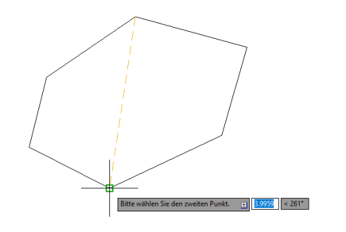
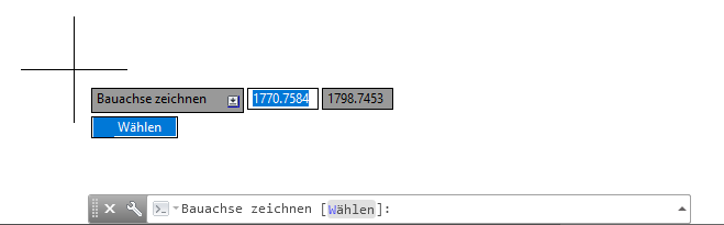
Any point can be selected to define the route. It is also possible to use an existing straight line with a maximum of two points. To do this, enter W or select in dynamic input Select.
- As soon as you have selected the second point or the straight line, the documentation is created in the drawing.
| without control line | with control line |
| 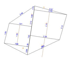 within the area |
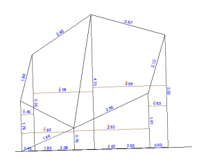 outside the area |
For complete documentation, the values of the outer edges should be displayed. To do this, activate in the area bending the options Generate surrounding edges and Dimension surrounding edges.