Table of Contents
triangulation
Command: TRIA
Description
The triangulation ![]() is a surface modeling from triangles (triangular meshing). The calculation is based on the Delaunay algorithm. This means that the triangles generated are meshed according to the so-called min-max criterion, so that the occurrence of acute triangular angles is avoided if possible.
is a surface modeling from triangles (triangular meshing). The calculation is based on the Delaunay algorithm. This means that the triangles generated are meshed according to the so-called min-max criterion, so that the occurrence of acute triangular angles is avoided if possible.
Because points are one-dimensional elements, they cannot be used to perform area or volume calculations. For a surface representation or calculation, the points must be connected by lines. The smallest area is made up of three lines - a triangle. A triangle always forms a flat surface that has a clear slope in space. Therefore, triangles are ideal for the simple representation of terrain surfaces and represent the basis for volume calculations.
Application
Create triangulation
| from Point set | Quick DGM> right mouse button on one Point Set> Triangulation With this method, a set of points from the drawing is used as the basis for a triangulation. |
| from modeling | Quick DGM> right click on a Modeling> Triangulation If modeling is used as the basis for triangulation, no point set needs to be created in advance. This is useful if, for example, a triangulation is to be created from the contour lines in the drawing. DATAflor CAD then creates a rectangular triangulation with four corner points that spans the entire area of the contour lines, using the smallest Z value (height) as the basis. |
| from triangulation | Quick DGM> right click on a Triangulation> triangulation If you need a triangulation without edges, this method can be used. With this option, the current status of the underlying triangulation is declared as fixed, which means that edge definitions can be inserted as given and no longer changed. This function is useful, for example, when you have edited the triangulation of the terrain to such an extent that the state optimally reflects the real appearance of the terrain. By creating the basis, you define the state as a starting situation on the basis of which planning can be carried out. |
| from Grid | Quick DGM> right click on a Grid> Triangulation For a very fine meshing, a grid can also be used as the basis for a triangulation, the amount of data increasing accordingly. |
If the creation of the triangulation is called from the Quick DTM, a triangulation is immediately created based on the basis used. This triangulation is then sorted under this basis in the tree structure of the terrain model objects.
When you use the triangulation from the Menu> Surfaces tab a window is displayed in which the Basics for the calculation of the triangulation. With Apply the triangulation is created and inserted into the drawing.
The triangulation is automatically zoomed to the limits of the screen.
Several DTM objects can also be selected for creating a triangulation, e.g. several sets of points (see chapter Edit triangulation).
Edit triangulation
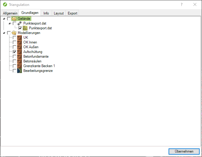
The basics of triangulation can be found on the tab Basics (Quick-DTM (AutoCAD based) > ![]() Info) can be changed. Point sets and modeling can be activated and deactivated here.
Info) can be changed. Point sets and modeling can be activated and deactivated here.
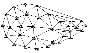
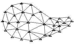
The option Remove edge triangles (Quick DTM > ![]() Info > tab General) automatically deletes all border triangles that contain an angle of less than 10 degrees. This often occurs when triangulating points that actually have no real relationship. The calculation may take longer for large point sets. In these cases, we recommend working with a processing limit (see modeling).
Info > tab General) automatically deletes all border triangles that contain an angle of less than 10 degrees. This often occurs when triangulating points that actually have no real relationship. The calculation may take longer for large point sets. In these cases, we recommend working with a processing limit (see modeling).
| Edge triangles present | Edge triangles removed |
 |  |
If there are not enough points in the set of points in some places, this can mean that the triangles of the triangulation do not correspond to the terrain. Corrections in the triangulation (e.g. swapping triangles) can be carried out with the available tools (called with the right mouse button). In order to obtain correct calculations, it is also possible to record slope edges. These can then be used as modeling (see modeling) can be used to calculate triangulations.
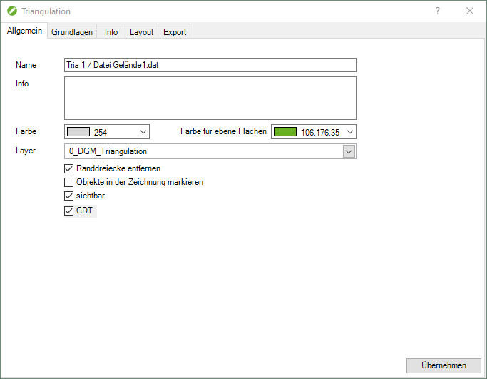
The option CDT (Constraint Delauny Triangulation) stands for the new method for calculating the triangles. With this method, a fast and precise meshing, including modeled edges, is generated. This is a great advantage, especially with high point densities.
Features
Layout tab
On the tab layout the color properties can be set. Triangles that lie in one plane, whose three corner points have the same height, can be displayed in different colors. The default setting is the color green.
You can also choose whether to display the triangulation with a color gradient to make height differences immediately visible. To do this, activate the option Derive color from height. The color gradient is defined by entering the start color and end color. The intermediate values are interpolated.
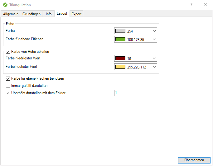
Triangulation can be used to analyze the existing triangulation Show too much with a factor. This is a purely optical representation in 3D space, without any influence on further calculations (e.g. profiles and volumes).
| Exaggeration by a factor of 1 | Exaggeration by a factor of 5 |
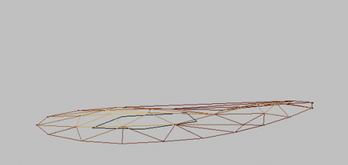 | 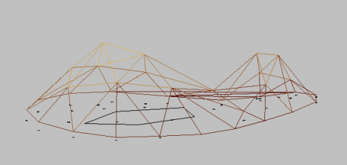 |
The name of the triangulation (tab General) is automatically filled with the default name.
The settings on the tabs General and layout can in the window Configuration (please refer Quick-DTM (AutoCAD based)) can be defined as a default for all further drawings.
Further steps
Layer structure
Difference body
Terrain cut
Profile group
contour lines
Grid
Analyses
Export of DTM data
Extract triangulation
Merge triangulation
Legend
Tools for editing
Swap triangles
Delete triangles
Interrogate
Insert as a point
Add as a point to the triangulation
Perspective view
Lift objects onto the surface
Layout plan
Create slope edges
Special modeling
Copy to AutoCAD mesh
Generate boundary line