Table of Contents
Edit documentation manually
Description
There may be areas in which deviations from the automatic documentation are desired or the automatically generated documentation is to be changed. There is a special function for this, which can be used to determine which support points and elements are to be used for documentation. The manual creation works in the same way as the editing of existing documentation. The only difference is that when editing, all required support points and Standard geometries (Triangles, trapezoids, etc.) are already present.
Application
- The object whose documentation is to be edited must be marked in the mass tree.
- Then the object with ZOOM LIMITS projected onto the screen and a dialog appears on the left with which the commands for editing the object can be accessed. Depending on the selected object (distance or area) and the documentation method set in advance (standard geometries or Gauss-Elling), the dialog contains different processing options, which are explained below.

Manually created or edited documentation is not updated or overwritten when the drawing object is changed or the documentation is created again. This is a protective mechanism so that complex edits are not accidentally deleted. In order to remove or update manually created or edited documentation, it must be accessed via [Clear] removed and with [Produce] be recreated. These functions are both in the context menu and in the dialog Documentation (Info dialog > ![]() documentation) available.
documentation) available.
Options for routes as well as for areas according to Gauß-Elling
Options for surfaces with regular geometries
 | The dialog corresponds to that for route documentation and documentation according to Gauß-Elling. In addition, there are a few options that are specifically required for a breakdown into standard geometries. These are: - Create triangles and squares - Deletion of standard geometries and arcs - Display of the already documented area |
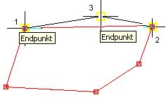
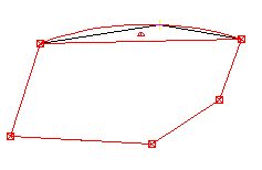
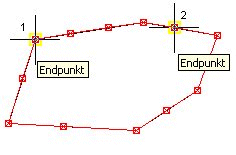
| Create | Triangles: After calling up the function, 3 points must be selected in which a triangle is then created. Either in the Claw clicked or it can be via the OFANG a point on the boundary can be selected, in which a support point is then automatically created.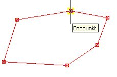  |
| Squares car: are trapezoids or rectangles, which are automatically recognized and also documented differently in the quantity report. After calling up the function, 3 points must be selected. Either the handles must be clicked or the OFANG a point on the boundary can be selected, in which a support point is then automatically created. The fourth point is chosen independently by the program on the boundary or added if it is not available. The base line for the calculation is the connection between the first and second point (L1). After selecting the third point, the program automatically creates a parallel connection to L1, which goes through point 3 and therefore defines point 4.  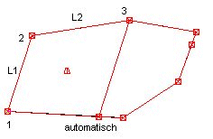 |
|
| Squares: are trapezoids or rectangles, which are defined by specifying 4 points. Either the handles must be clicked or the OFANG a point on the boundary can be selected, in which a support point is then automatically created. The base line for the calculation is the connection between the first and second point. With this method, the heights between points 1 + 2 and 3 + 4 are averaged so that the height of the square is obtained. The averaged height is used for the graphic documentation and the proof of quantity.  |
|
| Delete | Everything inside: Removes all regular geometries and arcs from the object. The points on the boundary are retained.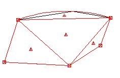  |
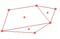
| Fill option | To check whether all areas have been recorded, the option To fill be used. The filling only refers to the display in edit mode and is not adopted in the drawing. 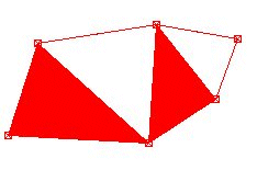 |
Switching between different options (e.g. deleting points after creating triangles) can be done smoothly. In this case, simply activate the desired option using the buttons.
The size of the icon handles is controlled by the slider. The symbol size can be changed during manual editing of the documentation using the slider at the bottom of the dialog.
The manual creation of a prism documentation is not possible because the prisms are clearly defined by the difference body.


