Table of Contents
Difference body
Command: CALCDIFF
Description
The function Difference body ![]() determines the volume differences between any two terrains. The basis can be two different surfaces (measurement of the existing site and measurement after a construction project) or two states of a site (with and without modeling). In the latter case you can also use the function directly Quantity difference use. This function can be selected as soon as a modeling has been assigned to the triangulation.
determines the volume differences between any two terrains. The basis can be two different surfaces (measurement of the existing site and measurement after a construction project) or two states of a site (with and without modeling). In the latter case you can also use the function directly Quantity difference use. This function can be selected as soon as a modeling has been assigned to the triangulation.
In addition, volume differences in relation to horizons can be calculated without having to create an additional surface. The difference body for the entire area is calculated in relation to a plane (horizon).
The difference body is an independent object and is automatically adjusted when changes are made.
Application
Create difference bodies
Quick DGM> right click on a Triangulation> difference field
Quick DGM> right click on a Triangulation> quantity difference
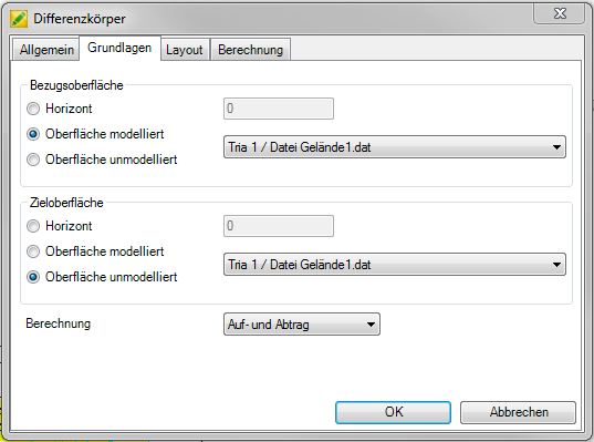
First select on the tab Basics the calculation bases. The difference field is the result of the intersection of the Reference surface familiar with the Target surface. You can choose between triangulations and horizons.
For triangulations, the options unmodeled and modeled are also available. Thereby means modeledthat the basic state including changes due to inserted modeling is used for the calculation of the surface. Unmodeled works with the original terrain with no inserted modeling. Examples of this are explained below.
Then select at calculation from what is to be calculated for the difference field: Application and removal, only order or only removal. The selection made here will be taken into account in the later process, e.g. when creating a profile or for the quantity verification.
With the confirmation [OK] the difference body is created below the selected triangulation.
The information about the determined quantities (e.g. volume order and removal) can be found on the tab Info (Quick DTM> Info).
Example 1 - Volume calculation when planning a new surface
A set of points is triangulated and then a model is created and inserted. So the triangulation is for DATAflor CAD in two states: unmodeled (direct triangulation from the point set) and modeled (modified triangulation by inserting a modeling). There is no need to create an additional triangulation as a reference surface for the calculation. The difference body is calculated with the following settings: Reference surface = triangulation 1 (option unmodeled) and target surface = triangulation 1 (option modeled) - The function Quantity difference should be used.
Example 2 - Volume calculation for comparison before / after
An existing site is recorded and the point set is triangulated. Then a second site survey is created and this is also triangulated. The triangulations do not have to be congruent in the plan view, the program automatically determines the areas in which there are overlaps and differences can be calculated. However, it is better to have congruent areas, as otherwise undesired deviations (mass reductions) can occur. Triangulation 1 (option unmodeled) and triangulation 2 (option unmodeled) would now be used to calculate the difference field.
Example 3 - Volume calculation on a horizon
There is a triangulation in the drawing (modeled or unmodeled). The volume should now be calculated for an area (e.g. an excavation). However, not the entire volume is required for this, but only the volume from the surface of the terrain up to a height of 94m for the first construction phase. This can be solved with the horizon. The volume is calculated with the following settings: Reference surface = triangulation 1 (option modeled / unmodeled - depending on the terrain) and target surface = horizon 94. After selecting the horizon, enter the height for the plane in the field.
Features
Layout tab
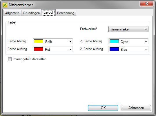
On the tab layout the color properties can be set. You can the Colors for order and removal. The default setting for order is always red and for removal yellow. For the color gradient you can choose between not applicable, Prism height or Prism volume in% choose. Prism height shows the thickness of the prisms with a gradient, whereas Prism volume in% the volume used. The color gradient is defined by entering the start color and end color. The intermediate values are interpolated.
The Name of the difference field (tab General) is automatically filled with the default name.
If the option is activated Mark objects in the drawing (Tab General), the object marked in the Quick DTM is activated in the drawing at the same time. With larger DTM objects, the delay caused by the marking of the object can be eliminated by deactivating this option.
The settings on the tabs General, layout and calculation can in the window Configuration (please refer Quick-DTM (AutoCAD based)) can be defined as a default for all further drawings.
Calculation tab
When calculating differential bodies, very small prisms can arise that are not relevant for determining the volume. This can be done with the option Filter small prisms (on the calculation) are automatically removed, which can significantly increase the clarity.
With Show all prisms in the differential body but these can be displayed graphically. If the option is deactivated, the corresponding prisms are not generated.
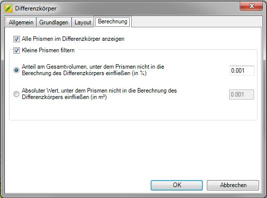
With the option Share of the total volume under which prisms are not included in the calculation of the differential field (in%) you can set the percentage threshold for removing prisms, or you can use the option Absolute value under which prisms are not included in the calculation of the differential body (in m³).
As soon as a difference of more than 1% of the total volume is calculated on the basis of the filtered out prisms when creating a differential body, a message appears with the corresponding quantities.
This information can later be found on the tab Info (Quick DTM> Info).
Within the Generation of profiles (please refer Terrain cut and Profile group) become all prisms in the calculation includedregardless of which value is used for filtering prisms.
Vertical edges of prisms are not generated as a 3D surface (example difference calculation on a horizon). This reduces the calculation time enormously. When visualizing with the command RENDER these surfaces are covered anyway.