Table of Contents
contour lines
Command: ISOLINES
Description
contours ![]() (Contour lines in the terrain) are derived from a triangulation, a grid or from a difference body and are located in the hierarchy below the corresponding terrain object.
(Contour lines in the terrain) are derived from a triangulation, a grid or from a difference body and are located in the hierarchy below the corresponding terrain object.
When calculating isolines, a precisely defined terrain height is entered as a line on the surface or on the differential body. In the case of triangulations, the representation is accordingly very straight, whereby the grid usually results in a rounding.
Application
Create contour lines
Quick DGM> right click on a triangulation, Grid , or Difference Body> Contour Lines
Edit contour lines
If you are the Info (please refer Quick-DTM (AutoCAD based)) to open the contour lines on the tab contour lines change the properties.
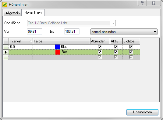
In the area From ... to the smallest and largest Z-value (height) within the selected surface is displayed. The area in which the contour lines are to be created is also defined here (e.g. only between 90.00 and 100.00 m).
You can click in the bottom line of the table to create a new one interval to be determined. When you get into the box for the Color a corresponding color can be selected from the list by clicking. The intervals are automatic Active and in the drawing Visible.
If contour lines are calculated in relation to a triangulation, the display is very "angular" because the triangulation is not rounded off. To get smooth contour lines, use the function for rounding off isolines. To do this, tick the column Round off.
| Before | later |
 |  |
Due to the rounding off, the visible course of the contour lines can deviate from the calculated course. Therefore, the intensity of the rounding of very weakly round off (Very close to the calculated course. The contour lines are only rounded off a little in the corners) up to round off very strongly (Strong deviation from the calculated course. Very round representation of the contour lines).
When confirming with Apply the contour lines are calculated and inserted into the drawing.
The Name of the contour lines (tab General) is automatically filled with the default name of the original object.
The settings on the tabs General and the interval gradations on the tab contour lines can in dialogue Configuration (please refer Quick-DTM (AutoCAD based)) can be defined as a default for all further drawings.