Table of Contents
Combine height points to a point set
Command: PSET
Description
The command Combine height points to a point set ( ) generated from DATAflor A new set of points is added to the surface elevation points that exist in the drawing.
The elevation points must be created manually beforehand (command DIGIP), derived from drawing elements (command EXTRACT) or read in as a file (command PIMPORT).
Application
- After calling the command you will be asked to select the corresponding height points in the drawing.
- After making the selection with Enter or with the right mouse button, a dialog opens in which the properties of the new point set can be defined.
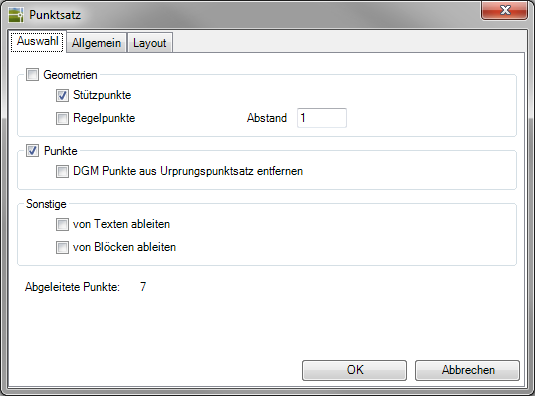
- On the tab selection in the field of Geometries you can set whether the points should be generated as control points and / or support points. The derivation of the bases is enabled by default.
- If you have selected points to generate the point set that are already contained in another point set, then in the area Points the option Remove surface points from the origin point set to get voted. Then the elevation points are deleted from the point set and are only part of the current point set.
- On the tab General one can Name and Info can be entered. Give the point set a distinctive description. This gives you a better overview if there are several sets of points. This name is also the default setting for all DTM follow-up objects.
The properties for color, layer and visibility in the drawing can also be set here. - On the tab layout can you use the Point labeling define, as well as the number of decimal establish. This setting can be changed later.
- With the confirmation [OK] the point set is created and inserted into the drawing.
Only with DATAflor Elevation points generated by CAD commands can be used to create point sets.
Features
Control points (Selection tab) means that an interval can be set in which height points on objects are removed (e.g. useful for digitized contour lines). The derivation of the control points always takes place in the processing, not in the projection. At Bases a derivation takes place via the pick points (linear objects) or from the base points (blocks and points).
| Control points: NO | Control points: YES |
 |  |
Point labeling (Layout tab): The points can also be assigned the coordinates of the current coordinate system (UCS coordinates) are labeled. The lettering is also used for Data exchange to Excel, into a ASCII- or CSV file exported. This function is used, for example, when setting out with the Leica Total station required.