Table of Contents
Gradient mesh
Command: GNET
Description
With the three-dimensional  Gradient mesh ceiling height planning can be implemented. The defined dependencies of the points from each other and from the terrain connection are automatically taken into account during planning and resulting conflicts are displayed.
Application
In the following application films you will see how you can create heights and slopes and how you can change the dependencies between the points, thus creating a ceiling height plan for a parking lot.
Gradient planning complete
Gradient planning in detail
Get to know the options for setting elevation points and the options for displaying the gradient network.
Get to know the functions for creating slopes. See how to change point heights and what effect this has on pinned and unfrozen slopes.
This film describes the functions of the symbols at the points and on the slope. You will see how to change the slopes in the slope network and how to set the reference point.
Features
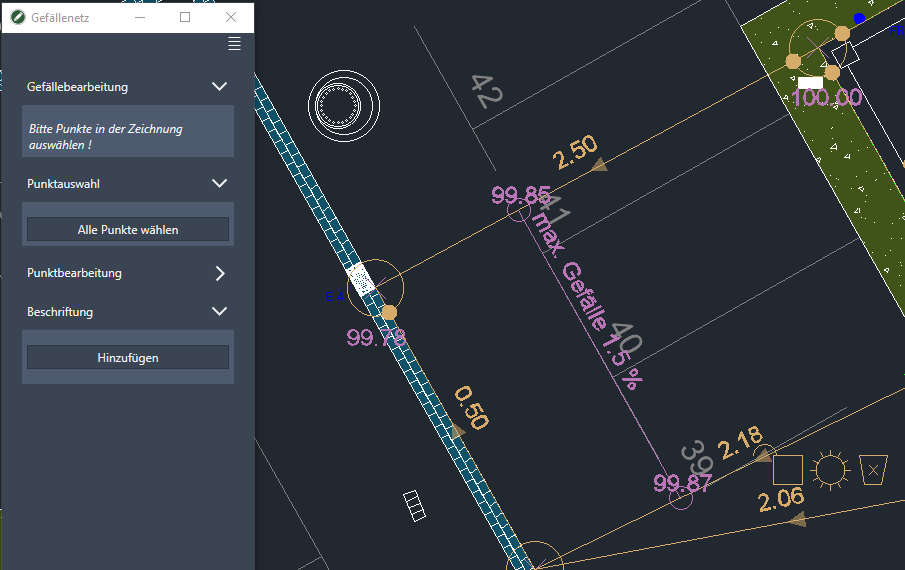
On the one hand, the functions for the slope network can be called up via the window; on the other hand, editing is also possible directly on the slope network using dynamic input.
Be careful when creating using Dynamic input on the display in the command line.
To use the function, enter the appropriate capital letter.
Create a slope
- Start by entering the value for the Height.
- Click in the drawing to create points at the appropriate elevation. Also use other heights for point creation.
- Subsequently [Start] The slope processing.
- Click the point from which you want the slope to start.
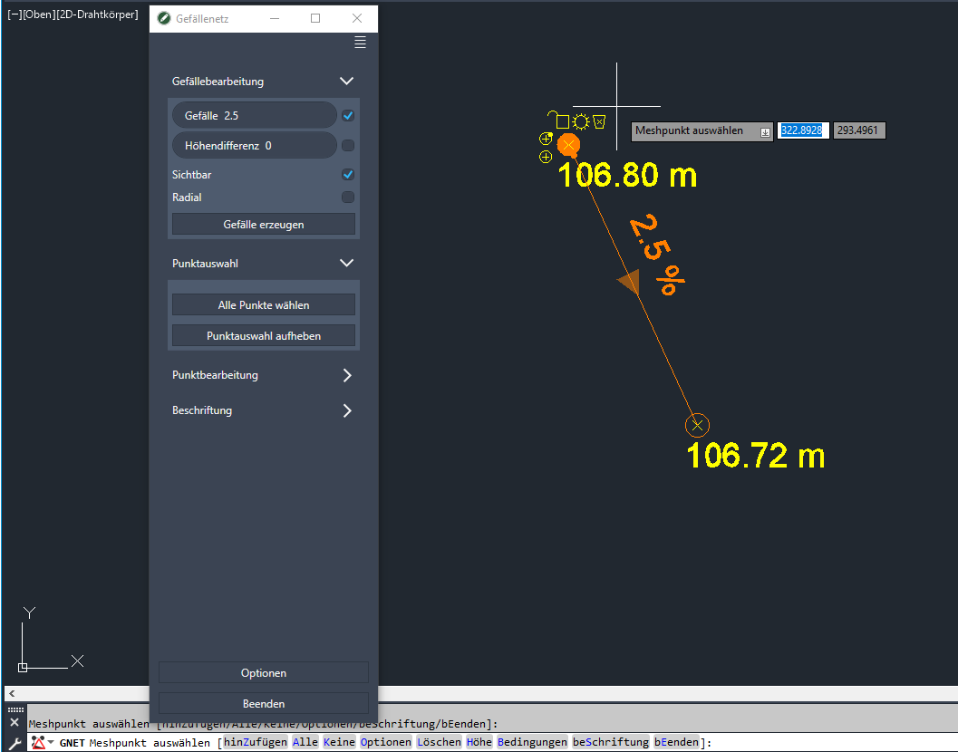
- The functions for slope processing appear in the window. Enter gradient or one Height difference in the field and activate the use of the relevant option.
- Once you hit the [Create slope] you can create slope lines in the drawing by clicking on existing points or on new points with the selected setting.
Other functions
| Automatic slope | This option is available for a slope path that has already been created. After selecting a start and an end point, all slopes between these two points can be adjusted. |
| Visible | If the option is deactivated, a slope is generated which is only visible in the edit mode. |
| Radial | This option appears when a Point was selected. Starting from this, points can then be generated in the form of rays. see also chapter below: Funnel slope |
| Closed | This option is displayed as soon as the options for slope and height difference are deactivated and at least 3 points are selected. A closed linear slope is created. |
Linear gradient
To create a linear slope, select the desired points (if necessary with the function [Select all points]) and then click [Create slope]. Slope lines are automatically created between all selected points.
There are the options gradient and Height difference deactivated, the slopes are calculated based on the heights of the points. The slopes are not locked, so changing the point height changes the slope value.
Funnel slope
- Enter the height for the funnel and put the point on the drawing.
- The outer points can then be defined with new heights.
- click on [Edit gradient] and select the funnel point.
- Activate the option Radial.
- click on [Create slope]to select the outer points.
With the option Radial Unfixed slopes are created so that they change as soon as a point is moved.
Process slope
As soon as the mouse pointer is near the objects, symbols appear at the points and on the slope labeling.

To use the symbols, the slope generation is allowed not be active. Go first [Back] for point selection.
| Lock | Locks the selected slope or height. If the slope is blocked, the height of the adjacent point changes. The slope changes when the point is blocked. |
| Visible | Points and slopes can be switched invisible so that they are only visible in edit mode. |
| Delete | Deletes the selected point or slope. |
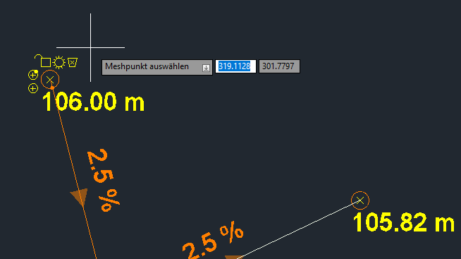
| Plus with marker | Starting from the selected point, a new slope with fixation is created. The new point is created using the initial height and slope value. A marker in line color appears at the starting point. The marker shows the point from which the dependency in the corresponding direction starts. |
| More | Starting from the selected point, a new slope is created without fixing. Changing the height of the new point leads to a change in the slope value |
Change height / slope
To change a height or a blocked slope, click on the text with the mouse pointer. Then enter the new value and confirm it.
Pay attention to dependencies (marker at the starting point). Locks on the slope or at an adjacent point may prevent adjustment.
Label
With this function you can insert a label between two slope lines. For example information when a certain gradient must not be exceeded.
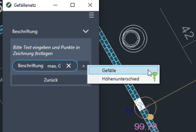
- Select under Caption Add.
- Then enter the labeling text or select one of the variables.
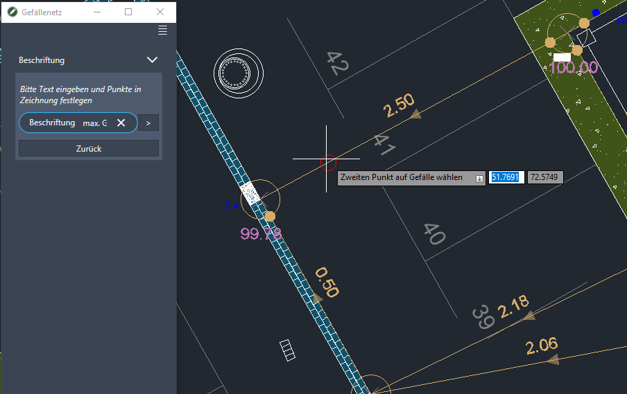
- First select the start point on one slope line and then the end point on the other slope line.

- A line with two labeling points and the slope labeling is automatically generated.


Options
The appearance of the falls can be determined via the [Options] control.
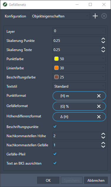
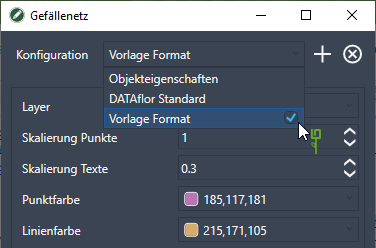
The illustrated Property are first used in drawings from the configuration DATAflor Standard generated. Changed object properties can be accessed via [To save] transferred to the current gradient network or via the + can be saved as your own template. This configuration can then also be used as the standard configuration. To do this, check the appropriate box in the selection list.
In the fields Point format, Slope format and Height difference format become the variables {H} and {G} used to display the corresponding point heights and slope values. There is also the option of entering text as a prefix or suffix.
With the option Align text to UCS the point heights are aligned to the selected coordinate system. The gradient values are always aligned according to the gradient line.
Will the option Fixed scaling On, the slope mesh annotation objects are not scaled in the viewport.
Use in the DTM
The sloping edges can be integrated into the Terrain model take over, for example, to perform volume calculations. Further information on the procedure can be found in the relevant chapters.
- Open thatQuick DGM.
- Create a modeling with a constrained edge, for which you select the gradient mesh.
- Finally, you bind the modeling with the slope mesh to the triangulation .