Table of Contents
modeling
Command: Kante
Description
You can use this function to create models, for example to define slope courses.
Modeling can be used individually or in combination with point sets as a basis for calculating a triangulation be used. As a separate basis, modeling is useful, for example, when a terrain model is to be developed from the contour lines of a topographic map. This also significantly reduces the amount of data.
One or more edges with different types of edge types can be defined within a modeling.
Modelings are not assigned to a specific triangulation in the object hierarchy and can therefore be part of several triangulations.
Modeling represents a special form of modeling Processing limit represents:
This is already in the group Modeling available. With this modeling, the option is Delete terrain outside of the outermost edge activated. Edges are to be added to it, which automatically limit the processing area for all surfaces.
Application
Create modeling
Quick DGM> right mouse button on the group Modeling> Modeling
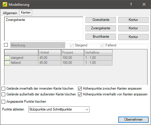
To add there is for the Borderline, Compulsory and Breaklines (see Chapter The different types of edges) two different ways of recording.
With the respective button you will be asked to select the corresponding objects from the drawing. The selection must go with Enter or with the right mouse button. Via the button [Contour] a contour derivation can be created for each type of edge. This is not associative.
The Breaklines the connection side must also be selected after the selection. The Offset width at break lines can be done in the configuration (see Quick-DTM (AutoCAD based)) To be defined.
Lines, 2D and 3D polylines, splines, arcs and circles can be used to create edges. In the case of constrained edges, points can also be inserted as constrained points. Circles, arcs and splines are inserted as polygons with the number of sides per full circle or the chord length in percent of the radius. This is done in the Basic settings performed.
Put the tick in front embankment (see Chapter Definition of embankments) you can set whether a slope should also be calculated for the new edges for the connection to the terrain. However, this option only applies to constrained edges and has no effect on other edge types. Instead of slope, you can also select multi-slope from the list (see Chapter Definition of multi-slopes) choose.
In addition, the embankment can be used as modeling only Increasing, just Falling or Increasing and Falling To be defined. Is preset Increasing and Falling.
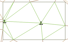
With the options Terrain within the innermost or delete outside the outermost edge the terrain area can be defined for the calculation and display. These options apply to all edge types.
 Original site |  Option Delete terrain within the innermost edge activated |
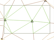
 Option Delete terrain outside of the outermost edge activated |  Option Delete terrain inside the innermost and outside the outermost edge activated |
With the options Elevation points within edges or Adjust height points between edges the adjustment of the height points can be influenced. These settings are made in the constrained edge area (in the following topic The different types of edges) explained.
The options Delete adjusted points and Derive points influence the calculation of the triangles within the modeling.
Delete adjusted points removes the points that were adjusted in height by the modeling.
 Original site | 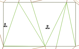 Option Delete adjusted points activated |
Derive points adjusts, depending on the setting, the number of derived intersections on the modeling.}
 Derive points Support points and intersections (previous behavior) |  Derive points bases |  Derive points Support points and control points at a distance of 1 |
The selectable options for deleting the terrain and for adjusting the elevation points relate to the entire modeling and not to the individual edges. In order to use the options for individual edges, these must be stored in different models.
If the modeling dialog is opened with [OK] finished, the modeling is created under the Modeling group.
Use modeling
The modeling can now be used as a basis in a triangulation. To do this, right-click on the modeling in the Quick DTM and triangulation choose.
Or you can add the modeling to an existing triangulation. Do this on the tab Basics (Quick-DTM (AutoCAD based) > Info button) activate the created modeling.
After confirming with [Take over] the edges of the modeling are inserted into the triangulation.
Edit modeling
On the tab bending (Quick-DTM (AutoCAD based) > Info button) you can zoom in on the edges of the modeling and these Delete. To do this, right-click on an edge. As soon as you click on an edge, it is marked in the drawing.
Features
Definition of embankments
When creating constrained edges, a slope can optionally be set, which then through DATAflor CAD is calculated automatically and inserted into the terrain.
Application
- In the area embankment the incline and descent can be entered using various parameters. It is possible to enter via Shop, percent or relationship, whereby the input fields update each other. The fields have the following relationships:

- After confirming with OK the defined settings for the modeling are adopted.
Laying down the embankment is on everyone Forced edges applied.
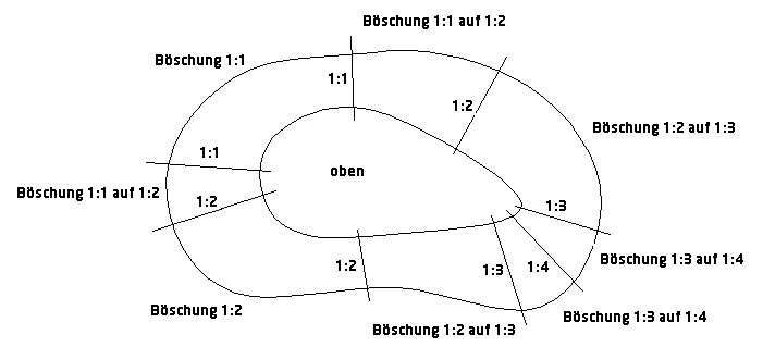
Definition of multi-slopes
Multi-slope represent a special type of slope. It differs from normal slope in that different inclines and slopes can be set within one slope definition. With this, for example, the modeling of a landfill can be solved very easily:
Application
- To define a slope, click in the empty table row.
- Now you have to click into the drawing. The slope definition is plotted perpendicular to the constrained edge.
- After completing the entry, the dialog opens again and the definitions are listed in the table.
- To the Slope or gradient To change a definition, the field must be marked and the new values entered. With [Take over] the definition is adopted in the modeling.
In order to Definition zu remove, highlight the line and press the button Del. Confirm your selection with Ja.
Further steps
The different types of edges
Different edge types can be used in the terrain model, which have different effects on the calculation and the appearance of a surface (triangulation).
An inserted Boundary edge Initially, it has no effect on the calculation of the surface, but together with constrained edges it can influence its calculation. Forced and broken edges however, always have an influence on the calculation.
 | Initial Situation |
Border edges - no change in the course of the terrain - inserts additional triangles and creates a new area |
|
Forced edges - Change of the terrain |
|
Breaklines - Change of the terrain - always creates a vertical slope |
Boundary edge
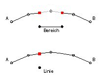
Areas of application: Subdivision of the surface into terrain areas (e.g. processing area), as well as for inserting predetermined breaking points for calculations and visualizations.
| Spatial limitation | Together with the option in the modeling dialog to delete terrain inside or outside of edges, the terrain can be precisely delimited with a boundary edge. |
| Predetermined breaking points | A change in the triangulation, which is caused, for example, by a constrained edge without a slope definition, expires at a defined boundary edge. |
| Visualization | Subdivision of triangles for the representation of different coverings and assignment of different colors and materials when rendering. |
 | closed border edge - Drawing object Z = 0.00 - An additional predetermined breaking point is created - additional area is created |
| open border edge - Drawing object Z = 0.00 - An additional predetermined breaking point is created - no additional area |
The spatial position (height) of the drawing object, which is to be defined as the boundary edge, has no influence on the creation of the boundary edge. Therefore, the drawing elements do not have to be lifted onto the surface first, but can have the height information Z = 0.00m, for example. This reduces the processing effort.
Closed boundary edges create a new terrain area that can be colored in a different color, for example. Open border edges only create a predetermined breaking point (more triangles).
Inserted boundary edges themselves do not change the calculation of the terrain. In interaction with constrained or broken edges, a boundary edge can very well change the surface (this is explained under constrained and broken edges).
Forced edge
Areas of application: surface changes and slope calculations
The constrained edge is the most common type of edge. A slope definition can also be set here at the same time. Points can also be used to define constrained edges to define a plane.
When creating constrained edges, the current height of the drawing element is used. With the tool Model interactively this can be changed later. The drawing element may need to be defined before the edge is defined with the tools Edit the course of the line and Raise / lower objects be brought to the right height.
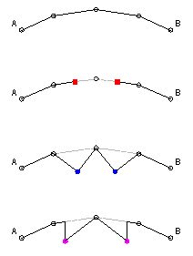
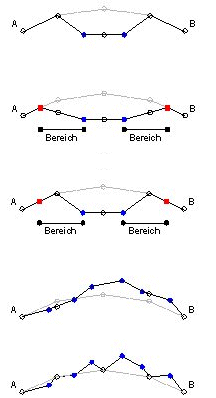
With the option Adjust height points within edges the automatic height point adjustment can be switched on and off, as shown in the following graphic.
 | closed forced edge - Adjust height points within edges activated - no embankment ⇒ it is adjusted outwards to the next height point |
| closed forced edge - Adjust height points within edges disabled - no embankment ⇒ it is adjusted outwards to the next height point |
|
| closed forced edge - Adjust height points within edges activated - Defined embankment ⇒ an outward slope is calculated |
|
| closed forced edge - Adjust height points within edges disabled - Defined embankment ⇒ an outward slope is calculated |
With one exception, open constrained edges behave in the same way as closed constrained edges. The height points are not automatically adjusted within the area of open constrained edges.
It should be noted here that the program regards a surrounding set of edges (eg closed boundary edge) as closed, so that height points can also be adjusted within open constrained edges.
Behavior of constrained edges in connection with boundary edges
 | closed constrained edge and border edges - Adjust height points within edges disabled ⇒ it is adjusted up to the boundary edges, as these are located in front of the height points |
| open forced edge and border edge ⇒ left is adjusted to the next height point ⇒ on the right is adjusted up to the limit edge, as this is located in front of the height point |
In the case of constrained edges without a slope definition, the connection to the terrain is usually to the next elevation point. However, if there is a boundary edge in front of a height point, this is considered the adjustment point.
Adjust height points between edges
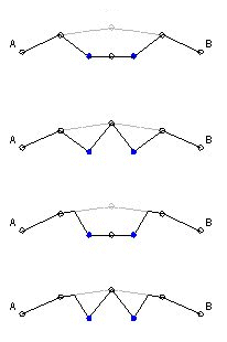
 | closed forced edge - no embankment ⇒ it is adjusted outwards to the next height point |
| closed constrained edge and surrounding closed border edge - Adjust height points between edges activated - The slope definition is no longer possible ⇒ It is calculated from the constrained edge directly to the boundary edge |
|
| closed constrained edge and surrounding closed border edge - Adjust height points between edges disabled - A slope definition is possible ⇒ it is adjusted from the constrained edge to the next height point |
|
| several closed forced edges - Adjust height points between edges activated ⇒ all altitude points are adjusted |
|
| several closed forced edges - Adjust height points between edges disabled ⇒ all altitude points are included |
This option can be used to control whether elevation points located between different edges are included in the surface calculation.
If this option is activated, the program also evaluates a surrounding set of edges (eg closed boundary edge), ie all elevation points in the terrain are adjusted.
Breakline
Areas of application: Vertical slopes and steps in the terrain
In the narrower sense, a breakline consists of two edges (a constrained and an internal boundary edge) which, due to a very small offset, result in an almost vertical slope (wall). However, only one line is required to create a breakline; the other is automatically passed through DATAflor CAD created. Breaklines can consist of closed objects as well as open objects.
The current height of the drawing element is used when creating breaklines. With the tool Model interactively this can be changed later. The drawing element may have to be used before defining the edge with the commands Edit the course of the line and / or Raise / lower objects be brought to the right height.
For each drawing element that is defined as a breakline, it must be specified on which side the connection side (AN = connection to the terrain) of the breakline should be. On the side that is selected as the connection side, a second edge (an internal boundary edge) is automatically created at a small distance.
The distance can be set in the configuration (see Quick-DTM (AutoCAD based)) To be defined. The default setting for the option Offset width at break lines is 0.001 (= 1 mm).
The initial drawing element is now inserted into the triangulation as a constrained edge, the offset drawing element as an internal boundary edge (at the original height of the terrain).
With the option Adjust height points within edges the automatic height point adjustment can be switched on and off, as shown in the following graphic.
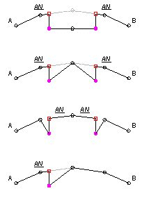 | closed breakline - Adjust height points within edges activated - Terrain connection outside |
| closed breakline - Adjust height points within edges disabled - Terrain connection outside |
|
| closed breakline - Terrain connection inside ⇒ it is adjusted to the next height point on the outside |
|
| open breakline - Adjust height points within edges has no function ⇒ it is adjusted to the next altitude point |
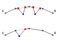
Behavior of open breaklines in connection with boundary edges
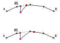 | open breakline and borderline ⇒ it is adapted to the next boundary edge |
| open breakline and borderline ⇒ it is adjusted to the next height point, as this is before the boundary edge |
In the case of open break lines, the connection side is specified on one side. The other side is usually adjusted to the nearest elevation point. However, if there is a boundary edge in front of a high point, this is considered an adjustment point - this also applies to closed breaklines where the connection to the terrain is on the inside.