Table of Contents
Configuration
Description
As soon as a file has been selected for import, the dialog Total station file preview via the menu Options can Configuration be adjusted.
Features
[OK] takes over the settings and applies them to new objects and when adding new properties. With the button [Abort] the dialog is closed without change.
Administration menu
Current settings can be saved and reloaded as a * .TSC file. With the call Load standard can the DATAflor Can be activated again. With Save as default will the DATAflor Presetting can be permanently overwritten.
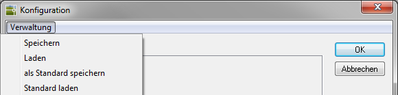
| Save | Saves the current settings as a single file. |
| Shop | Loads a configuration that has already been saved. |
| save as default | Saves the current settings in the file Default.TSC and thus overwrites the DATAflor Presetting permanent. This standard is now the default for all new drawings. |
| Load standard | In the case of manual changes, the file Default.TSC loaded and so the DATAflor Settings are reactivated. |
The configuration files are stored in the user directory of DATAflor CAD saved (see Important instructions > Chapter Data Backup). Each configuration corresponds to a file with the extension * .TSCso that files can also be exchanged easily.
Points tab
The content of the point labeling and the point symbol are set in the Point display area.
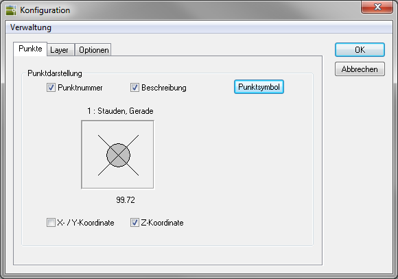
Point number corresponds to the number from the measurement.
Description corresponds to the coding.
X / Y coordinate and Z coordinate indicate the position in the coordinate system.
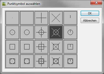
Choose a suitable one for the presentation [Point symbol] out. A later adjustment is with the command PYP is possible.
Layer tab
Here you can set detailed specifications for the layers that are used when importing the data.
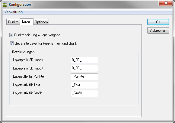
Point coding = layer specification takes over the automatic generation of layers in the import dialog.
With the option Separate layers for points, text and graphics the created objects are sorted on different layers.
In the area designations the layer defaults can be set, which are placed before (layer prefix) or after (layer suffix) in the created layers.
Options tab
Global settings for the interface can be made here.
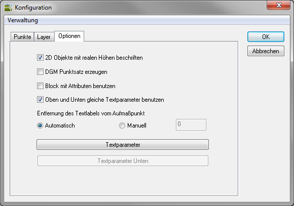
If 2D points are generated in the main dialog, the option Label 2D objects with real heights the measured height can be written to the objects, although the objects are all inserted into the drawing with a height of 0.00.
With the option Generate DTM point set a DTM point set is created after importing the data (requirement: terrain model). The following dialog appears:
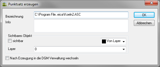
As soon as this option is activated, the point numbers supplied by the measurement are used as point numbers in the point set.
If a point set is formed from the imported points, the point numbers are also adopted.
see Combine height points to a point set
see Object manager > Documentation > Instructions for use > Chapter Use point ID from point files
Activation of the option Use block with attributes causes instead of DATAflor Measurement points (AutoCAD points with text labels) a block with attributes is inserted. The block file is called LPAPIN $$. DWG and is located in DATAflor CAD user directory (see Important instructions > Chapter Data Backup).
If a block is used, dots and text can only be placed on the same Layer inserted. You can also change the file accordingly.
If no blocks are used, the points are labeled with text labels. Is the option Use the same text parameters above and below deactivated, the layout can also be set differently. The configuration is done via the button [Text parameter] (please refer Text label).
The Distance of the text label from the measurement point can be done automatically or the distance is set manually by entering a value.