Table of Contents
Layer structure
Description
You can use this function to create new layers for the selected triangulation, which are required, for example, when building paths and terraces.
A distinction is made between two situations:
| On the site Here the individual layers are based on the chosen triangulation up added. With this function, for example, landfills or multi-layer structures can be created. If the triangulations of the layers are to be calculated, the upper Triangulations of the individual layers calculated. | 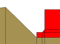 |
|
| In the area The individual layers are made up of the chosen triangulation down added. This function is used, for example, in road construction. If the triangulations of the layers are to be calculated, the lower Triangulations of the individual layers calculated. | 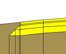 |
|
Application
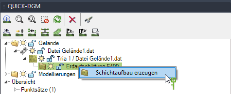
- Select the desired triangulation in the DTM tree and call it with the right mouse button Triangulation> layer structure on and choose whether the layer structure on the site or in the area should be created.
- In dialogue Layer structure you can either select an existing layer structure or create a new layer structure.
- To create a new layer, click in the dark gray area in the table below. Enter the Namur, the Thickness and Offset at, define whether the edge of the layer perpendicular or should run with a slope and select whether a triangulation or a difference body should be calculated for the layers. To change the columns, press the key Tab.
- On the tab boundaries you can define areas that should be left out if necessary.
- With Enter or [OK] confirm the selection. The dialog is closed and in the Quick DGM the entry for the selected layer structure is created.

- Call via the context menu create layers and then select all DTM objects.
- After confirmation, the new entries for the layer structure are created (triangulations in the specified number and the corresponding difference bodies).
Features
Shifts tab
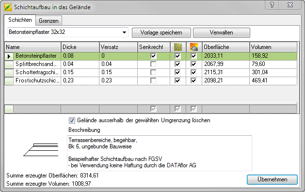
In the upper area of the dialog you can select an existing layer structure from the list or enter a new name for your layer structure in the field. With the button [Save Template] you can save your changes. The button [Manage] opens a dialog for managing existing layer structures, in which you can delete the existing layer structures or create copies.
The next area shows the individual layers with their settings:
| Name | Enter the material or the name of the layer here, for example. |
| Thickness | Define the layer thickness in meters. |
| Offset | Enter the offset in meters here. A positive value creates an outward offset. A negative value creates an inward offset. |
| Perpendicular | If the option is activated, the edge of the layer is displayed vertically. Otherwise, a slope is calculated based on the values for thickness and offset. |
| If the option is activated, a triangulation is calculated for the slice. | |
| If the option is activated, a difference body is calculated for the layer. | |
| Surface | The calculated surface of the layer is displayed here, provided the option has been activated. |
| Volume | The calculated volume of the slice is displayed here, provided the option has been activated. |
With a click with the right mouse button on the beginning of the respective shifts, the order can be adjusted or shifts that are not required can be deleted.
Is the option Delete terrain outside the selected boundary activated, then only the terrain within the boundary is calculated as layers. If the option is deactivated, the terrain outside the boundary is also used for the calculation.
In the lower left area, a Preview the layer structure shown. The preview can also be inserted into the drawing as a scheme. Right-click on the layer structure in the Quick DTM and choose Scheduling. You can then insert the scheme into the drawing with the mouse.
The sums of the surfaces and the volumes are displayed below the preview.
The sums of the triangulations and volumes as well as the individual values for surface and volume in the table are only displayed if the dialog is opened via the tree in Quick DGM (Quick DTM> Info) is called.
In the field Description you can store further information about the layer structure.
Notes on calculating the triangulations of the individual layers:
When calculating the layer structure, it is primarily a matter of calculating the individual volumes of the layers. In order to be able to calculate these difference bodies, the respective lower edges are made up not only of the base area, but also of the associated slopes on the next layer.
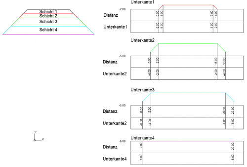
- The top triangulation (black in the picture) is not shown in the tree, it is only calculated internally. It consists of the original triangulation and the bevels on the lower edge1.
- The next triangulation (lower edge1; red) contains the base area of the previous triangulation and the bevels on the lower edge2.
- The following surfaces are calculated according to the same scheme.
- Since there are no more surfaces after the last surface (lower edge4; magenta), no more slopes are calculated for this surface. This triangulation therefore only consists of the base area of the previous triangulation.
During the projection therefore the area of the last triangulation corresponds to the previous triangulation. However, if you compare the surfaces in the Processing, then the area of the last surface is even smaller than that of the previous surface, since the slopes significantly influence the size of the surface. This is not an error in the program, but is due to the calculation of the triangulations of the layers.
With a layer structure on the site the surfaces behave the other way around.
Borders tab
In order to cut out areas from the layer structure (e.g. building edges), you can use the boundaries closed objects can be defined as boundaries.
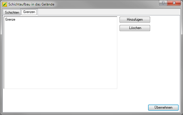
With the button [Add] you can capture existing, closed drawing objects as boundaries or boundaries with the right mouse button using the options contour (for existing, not closed objects) or To draw (for new, closed polygons).
With the button [Clear] limits that are no longer required can be removed from the list.