Table of Contents
BIM-Manager
Command: QBIM
Description
The  BIM-Manager allows you to ifc- Load files into the drawing and export them.

This manager is a prerequisite for working on BIM projects. Imported IFC files can be read in as a basis for planning. It is also possible to create BIM objects from simple drawing objects (see Creation of BIM objects) and this via the BIM-Manager to export. This guarantees your participation in the BIM planning process.
The organization buildingSMART International (bSI) has defined the “Industry Foundation Classes” (IFC), a globally accepted standard for the digital description of building models and monitors this with a certification process for the import and export of BIM data. A certified IFC interface is a prerequisite for participating in BIM projects.
The DATAflor BIM-MANAGER has Certification received from buildingSMART. All of the total of 900 tests were passed in full and with the highest possible quality. Despite tough competition from major software providers, the DATAflor IFC interface is the only one that supports all IFC concepts error-free and 100%.
The BIM-Manager is not part of the basic program, but is a separate paid module.
Application
- Open the BIM-Manager by clicking on the command in the menu Transportation or by entering the command QBIM.
- click on
 Load ifc files in the toolbox.
 - The dialog for selecting one opens ifc-File.
- Select a file and click to open.
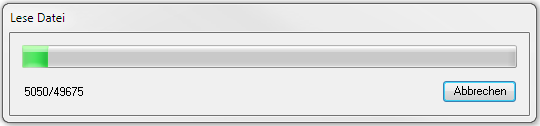
- The file is read.
- In the upper part of the BIM-Managers, the structure of the project is shown as a tree. The details (properties, material, etc.) of the selected node are displayed on the tabs in the lower part.
- In order to create the geometries in the drawing area, they have to be created on the respective desired node.
- With a click on the right mouse button, the option appears in the context menu
 Generate geometries.
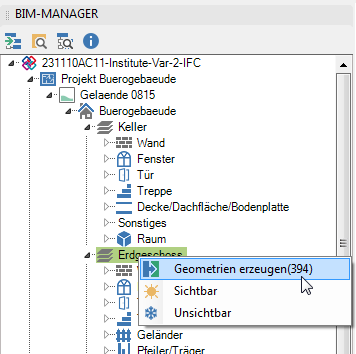
It is advisable not to create all the geometries of a drawing immediately, as this involves very large amounts of data. We recommend creating on the node Exterior components.
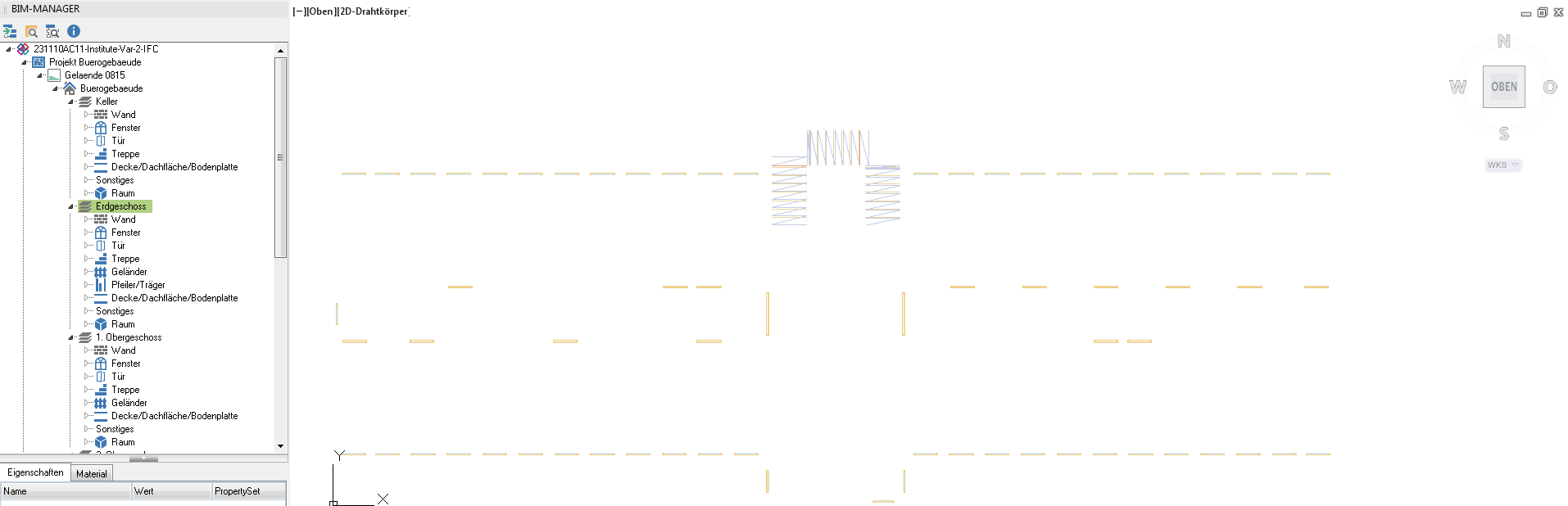
- Click on Generate geometries the geometries are generated and displayed in the drawing area.
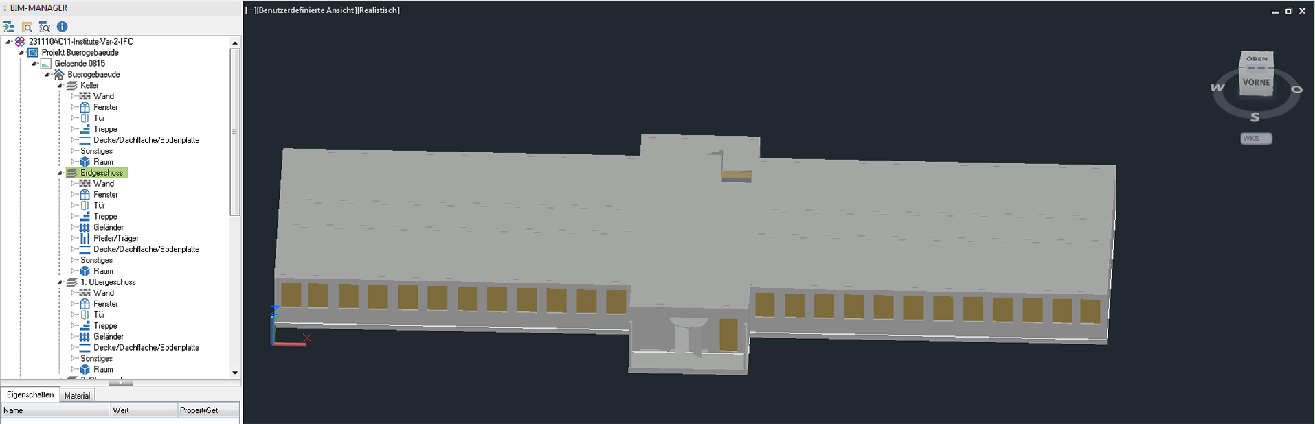
- The geometries are immediately created in 3D. With switching to the 3D orbit and the View> Realistic the 3D model is displayed.


Features
Switching geometries to visible / invisible
Geometries can be made visible and invisible via the context menu in the tree. This only works for geometries that have already been created.
Switch graphic variants on and off
By clicking on the project node  in the tree is in the lower part of the BIM-Managersa further one Graphics tab displayed. All graphic variants in the file can be switched on and off on this. The type and arrangement of the graphic variants is specific for each file.
toolbox
| Load ifc files | Opens the File selection dialog an ifc-Select file and open it. |
 | Zoom objects | Displays the selected object on the screen. |
 | Query object | By clicking on this command you can query an object in the drawing. You will then find this in the tree of the BIM-Managers displayed. |
 | Create IFC file | Creates an IFC file from the selected folder structure |
 | Info | Opens the Info dialog. In this you will find all detailed information on the component currently selected in the tree, such as properties, material, units, structure and history of the file. |