Table of Contents
Instructions for use
Some configuration settings (decimal places, consecutive point numbers, etc.) can be made globally via the Configuration and the options and not through the tab Documentation set (see Configuration and Options).
In order to obtain correct documentation, some rules should also be observed and followed.
Acquisition of 2D or 3D
When capturing objects in Object manager It must be taken into account whether the documentation is to be created in 2D (projection) or in 3D (development). If the objects are recorded in 2D (visible on ![]() Symbol), the quantities refer to Object manager always on the projection, even if, for example, the object is later lifted onto a DTM surface and the actual area is changed as a result.
Symbol), the quantities refer to Object manager always on the projection, even if, for example, the object is later lifted onto a DTM surface and the actual area is changed as a result.
Is a quantity takeoff in the Processing desired, the objects must be captured in 3D (visible on ![]() Symbol). Here you can choose between the development and the development on a surface (see objects > 3D-Objekte). If the reference area is changed during later work, the quantities in the object manager are automatically updated.
Symbol). Here you can choose between the development and the development on a surface (see objects > 3D-Objekte). If the reference area is changed during later work, the quantities in the object manager are automatically updated.
With the function Development on a DGM terrain surface the quantity takeoff can be carried out in the same way as in 3D planning, although the work is carried out in 2D.
Objects instead of contour derivation
When recording objects, recording as an object is preferable to recording using contours, if this is possible. When deriving the contour, it can happen that the support points of the contour are also used as support points for the documentation. Under certain circumstances, this can mean that, for example, the number of automatically generated standard geometries (triangles, trapezoids, etc.) is slightly higher.
Working with the command GPOLY (Boundary), which, similar to the hatching assignment, derives a closed polygon by clicking in the inner surface.
Edited and manual documentation
A manually created documentation or an automatic documentation that has been edited is not activated by the button [Produce] in the tab Documentation overwritten. Only if explicitly [Delete] in the tab Documentation is activated, the settings made manually are replaced by the automatic documentation. If the object in the drawing is changed, the documentation is not updated.
The object snap must be activated so that the object can be edited correctly. This setting can also be activated during acquisition by clicking OFANG is entered using the keyboard. Most of the time, they offer themselves in the dialogue Draft settings the options endpoint and Next point
Documentation of splines
When documenting splines, there may be deviations in the documented quantities because the splines must be broken down into individual arcs. There is no formula definition for splines in the REB.
The accuracy of the arcsecision can be found in the Basic settings be adjusted.
Edit documentation in the drawing
The graphic documentation can be edited directly in the drawing. To do this, the documentation must be marked, whereby the text entries are now blue Claw are displayed. The Text entries be moved. In the case of dimensions, this is done via the middle point. The angle can be changed with the two outer points. Documentation modified in this way behaves like manually edited documentation (see Documentation manual ⁄ edit), ie they are not updated if the original object is changed.
Documentation is provided with the command ORIGIN dissolved, it breaks down into individual objects and the documentation property is removed from the object.
You can also use the [copy into blocks], Blocks are generated. You can find this feature at the bottom of the tab Documentation. When the function is called, layers with the ending _BLK created. The documentation copied in blocks is located on these. These are drawing objects that are independent of the original object and can be edited as required.
Documentation according to Gauß-Elling in the high coordinate range
Often one works in a drawing in the high coordinate range (Gauß-Krüger). This is so that various planning partners can merge drawings and these are then perfectly coherent. This way of working is very common and is not a problem for normal work.
However, if masses are to be detected in a REB-compliant quantity verification using the Gauß-Elling method (using coordinates), it becomes problematic. The REB quantity certificate only allows six characters per field and up to three characters for the decimal places. The coordinates in the Gauß-Krüger area have seven places before the comma. The coordinates from the drawing therefore do not fit into a REB-compliant quantity statement - the coordinates are different. This means that the proof of quantity and the graphic documentation no longer match.
A REB-compliant proof is required not provided.
For example:
| Gauss-Krüger coordinates | Values in the REB quantity certificate |
| 4.527.900,541 / 5.686.733,943 | 527.900,541 / 686.733,943 |
| Correction by DATAflor CAD | |
| 900,541 / 733,943 | 900,541 / 733,943 |
Functionality
The use of a different reference point is permitted. DATAflor CAD provides a function that automatically solves this problem. The drawing itself does not have to be changed.
In the tab Documentation can another Reference point can be entered.
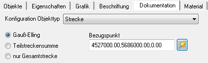
Here it is possible to "shorten" by entering the straight high coordinates, ie by entering 4.527.000, the coordinate is only documented as 900,541 for the example, instead of 4.527.900,541. Thus, the information is REB-compliant and can be understood without any problems.
Alternatively, by activating the button  a point can be selected directly from the drawing, which is then marked with a pick point and associated text field within the drawing.
If a drawing is to be documented with the coordinate documentation according to Gauß-Elling, it must be noted whether the drawing is in the high coordinate range (Gauß-Krüger).
Suppress duplicate documentation
For copied objects in Mass tree the duplicate creation of graphic documentation can be suppressed in a simple manner.
Functionality
With automatic documentation, all objects in Mass tree checked whether the original object has been proven by drawings. If this is not the case, every object is detected.
Accordingly, the original is provided with documentation by creating documentation or by writing a quantity certificate, all other objects are then not documented.
With the automatic generation of documentation, every object (including the copies) is shown graphically. This does not happen if the quantity certificate is generated directly or if only the original is documented before the quantity certificate is written.
Use point ID from point files
Point numbers can be generated for documentation. If over Free format (please refer Import point file > Use of the free import format) or the Total stations If a point file is imported, the point numbers for use in the documentation are generated internally.
The original point numbers from the point set file are used for the documentation when a graphic object from the point set file or an object drawn on the basis of the imported points is recorded in the object manager.
This is also possible if you use the function for point import Free import have used. (please refer Use point numbers).
The point numbers from point files are provided with a trailing * in the documentation.