Table of Contents
Grid
Command: GRID
Description
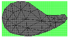
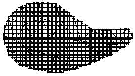
The grid ![]() is a surface consisting of a mesh of squares. An existing triangulation forms the basis for the calculation. The grid is also dependent on the triangulation for further processing.
is a surface consisting of a mesh of squares. An existing triangulation forms the basis for the calculation. The grid is also dependent on the triangulation for further processing.
Grids are mostly used for the visual representation of the terrain surface (visualization), since the terrain surface is displayed more evenly in contrast to triangulation. However, the grid is not suitable for volume calculations, since the interpolation is too strong for the display and the results are accordingly falsified.
Application
Create a grid
Quick DGM> right click on a Triangulation> grid
Edit the grid
The basics of the grid can be found on the Basics (Quick DGM > Info button) can be changed. Another surface can be activated here.
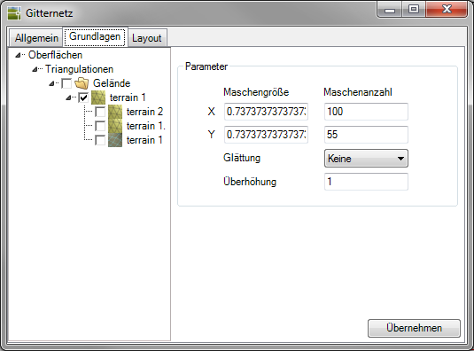
The following values can be set in the Parameter area:
| Mesh size / number of meshes | Mesh size: At this point you will be shown the size of the individual meshes (grid squares). This number is determined from the number of meshes and the dimensions of the selected triangulation. A number of stitches of 100 is set as the initial value, the mesh spacing is calculated accordingly. Mesh count: Here you enter how many meshes you would like to have for the selected triangulation in the X direction (columns). The number of stitches in the Y direction (rows) is derived from this. There is no limit to the number of meshes. Large values require longer calculation and insertion times, but increase the accuracy. The values for mesh size and number of meshes are interdependent. If one of the two values is changed, the other is automatically recalculated. |
| smoothing | Here you specify the smoothing of the surface to be created. The smoothing of the surface depends on the number of neighboring points of the triangulation included in the calculation. The following options are possible: none = 0, easy = 2, medium = 4, strong = 8 neighboring points. The more neighboring points are included in the calculation, the smoother the grid appears. If the option None is selected, the grid is projected onto the triangulation. If the smoothing is set to None, the height values of the grid nodes are calculated based on the triangulation. If another setting is selected for smoothing, as many points as the setting requires are also included in the calculation. |
| Cant | This number indicates the factor by which the ascertained height values should be multiplied in order to make the terrain more clearly visible. |
The option Apron visible (Quick DGM > Info button> tab General) creates a rectangular boundary using the smallest z-value (height) as the base.
| Apron visible | Invisible apron |
 |  |
Features
Layout tab
On the tab layout the color properties can be set. Meshes that lie in one plane, the four corner points of which have the same height, can be displayed in a different color.
You can also choose whether to display the grid with a gradient to make differences in elevation immediately visible. To do this, activate the option Derive color from height. The color gradient is defined by entering the start color and end color. The intermediate values are interpolated.
The Name of the grid (tab General) is automatically filled with the default name.
The settings on the tabs General and layout can in the window Configuration (please refer Quick DGM) can be defined as a default for all further drawings.