Table of Contents
Basic settings
Command: MCONFIG
Description
The command MCONFIG controls the automatic division of arcs into polyline sections, the setting of the coordinate system for the Google Earth interface and the selection of the layer for the contour lines.
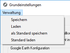
Features
| Save | Saves the current settings as a file. |
| Shop | Loads a setting that has already been saved. |
| save as default | Saves the current settings in the file Standard.CFRP from. This standard now applies to everyone new Drawings as default. |
| Load standard | In the case of manual changes, the file Standard.CFRP Loading. |
The files are stored in the user directory of DATAflor CAD saved. Each configuration corresponds to a file with the extension .CFRPso that the files can also be exchanged easily.
| OK | Accepts the settings and applies them to the current drawing. |
| Abort | Cancels the dialogue without making any changes. |
General tab
On the tab General On the one hand, the automatic division of arcs into polyline segments is controlled. This is necessary because DATAflor For example, CAD cannot place images on arcs. For this reason, and also for the creation of height points and triangulations, drawing elements must be broken down into linear sections within circles and arcs. Two different methods are available for the derivation.
Settings for the Google Earth interface can also be defined here. (see e.g. insert Picture) Please note that Google changed the terms of use and license at the beginning of 2017 and that it is no longer possible to use the Google Earth connection from Earth version 7.1.5.
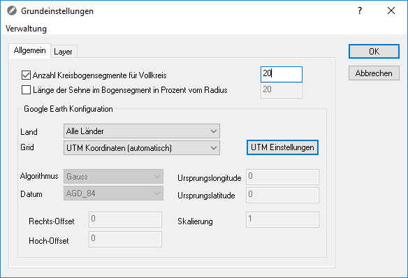
Number of arc segments for a full circle is a fixed value that creates the specified number of derived circle segments regardless of the object size.
Number of circle segments 20 | Number of circle segments 5 |
Length of the tendon in the arch segment is a relative specification in relation to the radius. The larger the radius, the more segments are created.
Length of tendon 20 | Length of tendon 50 |
The default setting of 20 usually delivers good results. Of course, the value can also be increased, but this can result in longer calculation times.
Google Earth configuration
Make settings here if your drawing is not in the specified grid. To do this, you can make a selection from the existing grids or make settings for a user-defined grid.
With the default UTM coordinates (automatic) the coordinate system used by Google Earth (Universal transversal Mercator) is supported.
The coordinate system set there (e.g. Gauß-Krüger) is still used in existing drawings.
You can change the coordinate system to UTM in this drawing:
- Choose for Grid the entry UTM coordinates (automatic) .
- About [UTM settings] indicate the zone and hemisphere.
- Activate the option Apply settings to drawingso that the current drawing is converted.
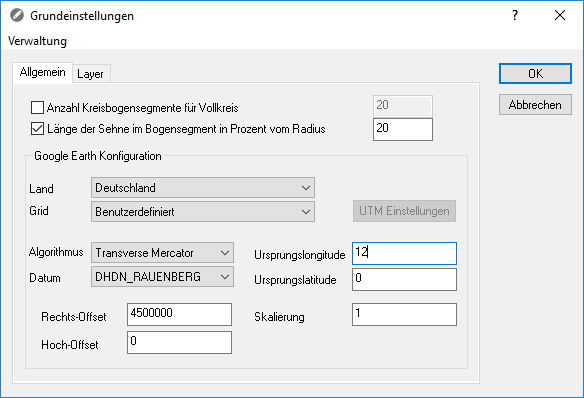
Example of a user definition
| algorithm | Projection methods that are used to transform three-dimensional geographic coordinates into two-dimensional (mostly Cartesian) coordinates |
| Date | Mostly only locally valid model for mapping the earth's surface. It is defined using the parameters of an ellipsoid and information about its position. |
| Origin length | Longitude of the center (central meridian) of the shown meridian strip (for Germany e.g. 6 °, 9 °, 12 ° and 15 ° East) The natural origin of the coordinate system is usually found at the intersection of the central meridian with the equator. In rare cases a latitude of origin is given, with the intersection of the central meridian with this latitude forming the natural origin of coordinates. |
| Origin latitude | Latitude of the natural projection center (of the natural coordinate origin) |
| Right offset | new easting value for shifting the natural coordinate origin, e.g. to avoid negative easting values (also called false easting) |
| High offset | new northing value for shifting the origin of coordinates (also called false northing) |
| scaling | Scaling factor along the central meridian |
Layer tab
On the tab Layer the layer on which the generated contour lines are sorted is specified. In addition, the object color for the contour lines can be selected.
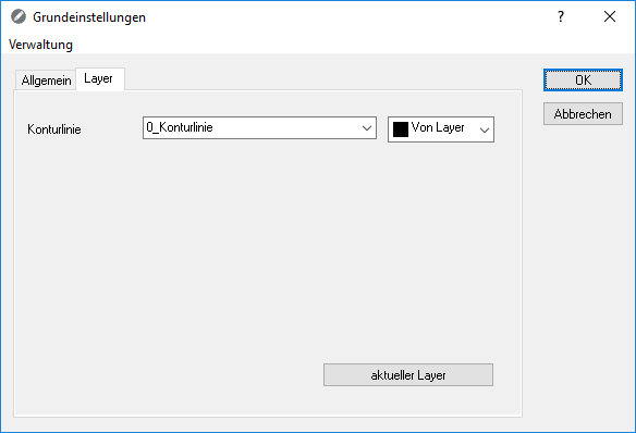
The given Layer is always a layer 0_contour line. However, an existing layer can also be selected or a new layer can be created.
Once you hit the [current layer] click, the selected layer is through "Current layer" replaced. When creating objects, the layer currently set in the drawing is used.
Will the Contour derivation from the Quick-Masses called (see Derive contour in Tool box base 1) and the option Prefix for layer designation is activated (see Options > General tab), then this layer prefix is added to the default layer selected here.
Except the default layer is on "Current layer" is set, then the actual current layer is actually used.