Table of Contents
Slope 3D surfaces
Command: FINCLINE
Description
With this command, drawing elements, starting from a point, are inclined in one or more directions in another plane. This function is used, for example, to provide a parking lot with a longitudinal and transverse slope before it is used as a modeling in a triangulation is meshed.
Application
- After calling up the command, the surface that is to be inclined must be selected.
- Then you will be asked for the Base point. The point of origin for the slope calculation is defined here. In the case of surfaces, a corner point is usually suitable for this.
- The following dialog then opens:

- With the option [produce] the direction and length of the desired slope is specified. After calling this option, the dialog closes and the gradient can be specified in the drawing.
With the option [choose] Alternatively, existing lines can also be selected.
- One or two slope profiles can be used to calculate the slope.
- The coordinates of the slope runs are temporarily displayed in the drawing and in the dialog.
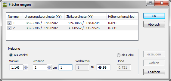
- If a slope is marked in the upper area, in the area Tilt the altitude profile can be entered.
The slope can as an angle about the definition of the parameters for Shop, percent or relationship respectively.Positive values always indicate a gradient, negative a gradient.
The command also allows the selection of other drawing elements, not just areas.Alternatively, you can also enter as height be made. The height is the relative reference to the start of the slope. The calculated result is shown above as the height difference.
- After selecting the options, the dialog with [OK] confirmed and the area automatically created.