Table of Contents
External data optimization
Command: DFOPTIM
Description
This function should be used when importing all external data that serve as the basis for your own planning. In this way, later planning errors can be significantly reduced, for example the problem of connecting lines that have different Z-heights, so that the new lines lead through the 3D space and deliver "wrong" results when queried (development instead of projection).
Imported Surveyor's Drawing - Isometric View
Corrected drawing elements with external data optimization - result: adjusted
Functionality
The use of the function relates on the one hand to selected objects (Color, height, etc.), on the other hand, global changes are made for the entire drawing (EXAMINATION, CLEAN UP etc.).
With [OK] the current settings are applied to the drawing, but the dialog is not closed. This means that not all conversions have to be performed at once. The results of the respective conversion can be found under Info can be called up in the menu. With [The End] shall DFOPTIM finished and the dialog closed. The information that would appear under Info is deleted from the memory. When the command is called again, the info display is empty and cannot appear in other drawings.
Configuration menu
Current settings can be saved as *.IMP-File can be saved and reloaded. With the call Standard will the DATAflor Setting activated. save as default overwrites the DATAflor Presetting permanent.
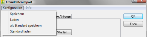
| Save | Saves the current settings as a single file. |
| Shop | Loads a configuration that has already been saved. |
| save as default | Saves the current settings in the file STANDARD.DFG from. This standard is now the default for all new drawings. |
| Load standard | In the case of manual changes, the file STANDARD.DFG Loading. |
| OK | Accepts the settings and applies them to the selected objects. |
| Abort | Cancels the dialogue without making any changes. |
The configuration files are stored in the user directory of DATAflor CAD saved. Each Configuration corresponds to a file with the extension *.DFGso that files can also be exchanged easily.
Info menu
After a conversion, the log of the changes can be displayed in a separate dialog with Info. The content in the dialog indicates the changes relating to the entire drawing in the upper area and the changes to the selected objects in the lower area.

If no conversion has yet been carried out within a command call, the setting is Info grayed out in the menu.
Selection tab
When selecting objects, you can choose between the options All and Select objects switch.
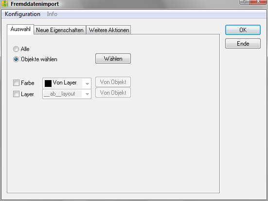
| All | If this option is selected, all drawing elements are selected (also on the layers with the status OFF, but not on those with the status FROZEN) |
| Select objects | If Select objects is activated, drawing objects can be selected directly in the drawing. over [Choose] change the selection, the previous selection will be deleted. |
The settings Color and Layer can optionally be switched on as a kind of filter function. Used for color or layer [From object] activated, the settings are automatically derived from selected drawing objects. Only the selected objects are changed.
New Properties tab
In the tab New features the conversion target for the selected elements is defined.
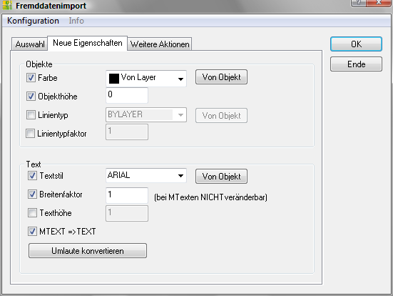
Objects area
| Color | A new color for the drawing objects is specified here. Will be there [From object] activated, the color property is automatically derived from a drawing object. |
| Object height | In addition to an elevation, an object can also have an object height (especially in building construction). With this option, the object height can be set to a uniform value (also 0). |
| Line type | A new line type for the drawing objects is specified here. Will be there [From object] activated, the desired line type is automatically derived from a drawing object. |
| Linetype factor | With this option, a uniform line type factor can be assigned. |
Text area
| Text style | A new text style for the selected texts is defined here. Will be there [From object] activated, the text style is automatically adopted from an existing text and entered as a default. |
| Breadth factor | With this option a uniform text width can be set. MTEXT must be converted with MTEXT⇒TEXT before you can assign a new text width. |
| Text height | With this option a uniform text height can be assigned. |
| MTEXT⇒TEXT | This option converts text that was generated from other CAD programs with a different code table (e.g. main street ⇒ main street). |
| Convert umlauts: | With the umlaut conversion you can convert German umlauts from texts into their international spelling (e.g. “ä” becomes “ae”). |
More Actions tab
In the tab Further actions Conversion targets for the selected elements as well as global settings for the entire drawing can be defined.
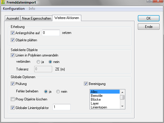
Area elevation
| Set the starting height to 0 | Here all elements can be set to a uniform Z-height, whereby the default setting is 0. Note that only one point is set at the specified height for elements that run diagonally through the room. The height difference within the object remains. |
| Flatten objects | Lines or elements with different Z-values are projected onto one height. Existing object heights remain. |
Selective Objects area
| Convert lines to polylines | Converts all LINES to POLYLINES and connects them if the Connect option is activated. Joining means that two polylines that meet at (or near) a point are converted into one polyline. If connect is activated and the tolerance is set to 0.00, the polylines must meet exactly at one point. The tolerance option describes the radius around the end points. If two polylines meet in this radius, they are connected without gaps. Constellations of more than 2 polylines in one point are not taken into account. For connecting it is also a requirement that the lines are on the same layer, have the same color, line type factor, line type and width. If only one requirement is not met, there is no connection. |
Global options area
The settings in this area relate to the entire drawing, regardless of whether drawing objects have been selected.
| Examination | Calls the command EXAMINATION on. This runs through until the result is 0. However, if no 5 is reached after 0 rounds, the test is ended. There is also the option of just displaying the errors without performing any remedial action. |
| settlement | Calls the command PURGE on. This runs through until nothing can be cleaned up. However, if after 5 runs there are still elements that cannot be cleaned up, the cleanup is ended. |
| proxy objects delete | With this option proxy objects can be easily deleted from the drawing. |
| Global linetype factor | With this option the system variable LTSCALE to be changed. |