Table of Contents
Edit the course of the line
Command: ZEDIT
Description
With this command you change lines, splines, polylines, circles, arcs and ellipses with regard to their Z values (heights), but in contrast to the command Raise / lower objects not the entire drawing object, but rather individual sections can be edited.
In a vector-oriented construction program such as AutoCAD, a line is described through a point, a direction and the length of the route. For DATAflor CAD has a simple line, a start point, a direction, a route length, a route gradient and an end point. A polyline is made up of several simple lines, whereby the end point of the first line is also the start point of the second, and so on. With a closed polyline, the end point of the last line is also the start point of the first line.
Application
- After calling up the command, the drawing element must be selected in the drawing. After the selection, the following dialog opens:
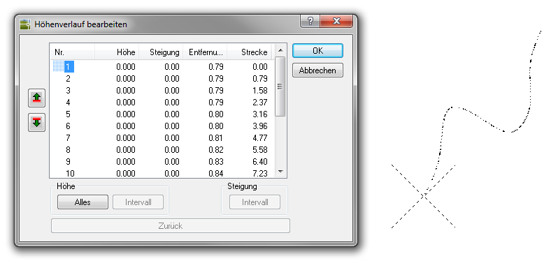
- In the table all vertex points of the selected drawing element are displayed with the following information: point number, height, percentage slope, distance in the projection to the previous point and distance to the first point. If a point is marked in the table, there is an automatic preview in the drawing.
The values shown in the table can be changed with Ctrl + C can be copied to the clipboard in order to then paste it into an editor and print it.
- There are now various options for changing the height within the drawing object: The options Single, All and Interval are available. Alternatively, the change in height can also be defined by entering an incline.
- With [Back] the last change is undone with [OK] the dialog is closed and the settings are immediately adopted in the drawing.
Features
| Point height> single | To increase the height of a single point on the drawing element change, double-click the point in question with the left mouse button. The following dialog opens, in which a height for this point can be entered.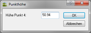 |
| Point Height> Everything | To align all vertices of the drawing element to one height change, click in the area Height on the button [Everything] and enter the desired height.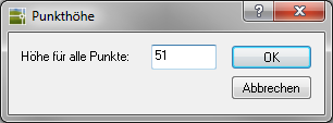 |
| Point height> interval | In the area Height can with [Interval] a start and an end height can be entered for a contiguous point range, whereby the heights for the included points are interpolated. First mark the starting point in the table with the mouse and then activate the up arrow if you want to mark up or use the down arrow if you want to continue marking down. Marked areas are shown with a green bar on the side. 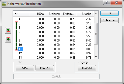 Call now with [Interval] in the field of Height Open the input dialog and enter the new height for the start and end point. Have you entered the new values and with [OK] confirmed, the percentage slope between the two points is calculated equally. Based on this calculation, the points in between are set to a new height. 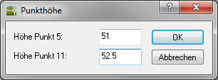 You can use this option, for example, if the start and end points are known as fixed connection points. In the case of a closed line, the last and the first point of the line are identical. As a result, it must also be specified for which direction the change to be made should apply, since the change can run in both directions. |
| Incline> Interval | In the area Slope can with [Interval] a slope between the start and end point can be entered for a coherent point range, with the heights for the included points being calculated. The slope can of course also be negative if it is a slope. First mark the starting point in the table with the mouse and then activate the up arrow if you want to mark up or use the down arrow if you want to continue marking down. Marked areas are shown with a green bar on the side. Call now with [Interval] in the field of Slope Open the input dialog and enter the gradient between the start and end point. Have you entered the new value and with [OK] confirmed, the percentage gradient between the two points is adopted. Based on this information, the points in between are set to a new height. 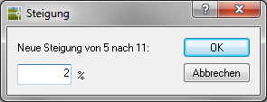 In the case of a closed line, the last and the first point of the line are identical. As a result, it must also be specified for which direction the change to be made should apply, since the change can run in both directions. |
The Calibration the decomposition of arcs per full circle can be done in the configuration (command MCONFIG) can be set. (please refer Basic settings)