Table of Contents
Mass tree
Description
The mass tree has two areas. In the area Current planning all objects of the current planning are sorted and in the area presets the specifications for the current planning are made.
Features
The following objects can be displayed in the mass tree in both areas:
The upper tree structure Contains the objects from the object manager and is used to record areas.
| Symbol | Description |
|---|---|
 | Groups that have the base for watering enabled |
 | Groups where the basis for irrigation is disabled |
 | Covered areas that are the basis for irrigation |
 | Recorded areas to which deduction areas have been assigned |
 | Recorded deduction area and area for which the option Basis for irrigation was deactivated |
 | Captured 3D surfaces from the Object manager, which are the basis for irrigation, calculation is done in 2D |
 | Captured 3D surfaces from the Object managerto which deduction areas have been assigned, calculation is carried out in 2D |
 | Captured 3D deduction areas from the Object manager and 3D areas for which the option Basis for irrigation has been deactivated, calculation is carried out in 2D |
During the lower tree structure the irrigation objects are created or managed.
| Symbol | feature |
|---|---|
 | Irrigation project / material specifications |
 | without assignment |
 | Water source |
 | Water pipe |
 | Nozzle sprinkler |
 | rotors |
 | Micro irrigation |
 | Valve circuit / hoses / pipes |
 | ECUs |
 | power cable |
 | Drip pipes |
 | Drip tube surface |
 | Valves |
 | Valve units |
 | water pumps |
 | Root irrigation |
Current planning
The upper tree structure shows the objects from the Object manager and is used to record areas that are required as a basis for irrigation planning. You cannot work with distances and volumes.
If a tree structure has already been created in the drawing, it is displayed here with all symbols.
Is not yet a mass tree in the Object manager exists, a predefined standard structure (see presets in the following chapter) is used with the corresponding graphic assignment. This structure is then also used as a mass tree in the Irrigation Manager displayed.
The irrigation projects are created and managed in the tree structure below.
In the group without assignment all objects used that have not yet been assigned and can be positioned variably are collected. The sprinklers and nozzles can be dragged and dropped into the irrigation project or sorted by selection from the drawing.
Are objects about Lines or Valve circuits connected to each other, they will be sorted automatically.
It can happen that irrigation objects are marked red in the tree. This is the case, for example, if sprinklers with different water outputs were selected or the pressure for the water source is too low. You should check the specified pressure values of your materials and, if necessary, use several valve circuits (see Create connections > Draw valve circuits).
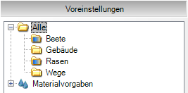
presets
In dialogue Irrigation Manager can the tree for that Current planning closed and the tree for that presets be opened.
In the tree above, you make the specifications that are to be used in the planning. Here you can create your own group structure, which is the default setting in the dialog for drawings Irrigation Manager is used. You then have the option of creating a differentiated water analysis for your recorded areas (see Create irrigation > Analyze water application).
The material specifications can be set in the lower part. The materials are grouped below the imported catalogs.
In addition to graphics and labeling, you can also set which materials should be taken into account and in which order. Read more about this under Tips and Tricks > Define material selection.