Table of Contents
Tabs
Information can be called up, functions can be used and properties can be defined in the tabs of the Irrigation Manager. Further information can be found on the individual tabs.
The tabs for the objects in the upper tree structure (see Mass tree) correspond in principle to those from the Object manager, however, not all tabs and not all content are displayed.
In addition to the presets defined tabs, come in the tree structure of the Current planning added tabs.
objects
In the tab objects you will receive a clear summary of the properties of groups in the current planning (see Mass tree > Current planning). The objects of the group selected in the mass tree are displayed.
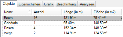
Pro Object the number of recorded areas / distances as well as the length in m and the area in m² is given.
If objects are marked and deleted in the tab, the entire group that is marked on the left in the mass tree is removed.
Material overview
The tab Material overview lists all materials of the chosen Irrigation project on. To do this, select the level of the irrigation project in the left area of the Irrigation Manager. Per material will be information about designation, Quantity, unity and Order number displayed.

Technical data
Technical data (such as length, water consumption, pressure) for each individual material are displayed in this tab. The content of the tab differs within the individual material types.
If not automatically available, a material can be selected here for the objects (see also Use materials > Select material). In the upper selection list you can use the symbol  select the type class and the material in the lower list.
Only those materials are displayed in the selection list which are in the default settings (see Mass tree > Preferences) have been activated.
Sprinkler
The option Housing regulates pressure is specifically in the sprinkler area (see Create irrigation > Detect sprinkler automatically) is available. This function ensures that the pressure of the sprinklers is not greater than the entered value, regardless of the operating and flow pressure.
The choice of housing and nozzle can be adjusted afterwards for all sprinklers. The selection can be made with the symbol  Lock, for example, to keep the settings for the automatically determined sprinklers. In some cases, changes can only be made if the selection is made with the symbol
  has been unlocked. This can happen, for example, if a certain sprinkler has been set.
If you click on the symbol  click, the selection dialog opens Put specific sprinkler. Here, a sprinkler can be added later Group, Housing and jet to be edited. Then run the function Recalculate the sprinkler (see Check and edit irrigation) for the valve circuit (or the entire calculation project) so that the water output is updated.

By day Height difference of the sprinkler to the water source influences the operating pressure, the height difference can be entered here in the tab. As soon as you save the value, the operating pressure and thus all data dependent on the pressure are adjusted.
If several sprinklers are to be assigned the same height difference, you can mark a higher-level node in the tree (e.g. valve circuit) and use the menu Extras the entry Enter the height choose. In the following dialog, enter the height difference, which is then passed on to all sprinklers below the node (see Check and edit irrigation > Enter height).
Valve unit
In the area of the valve unit, the valve circuits are listed in a table (see Create connections > Set valve unit or draw valve circuit). Information on length (in m), water consumption (in m³ / h), start pressure (in bar) and flow speed (in m / s) is displayed for each valve circuit.

Water source
For the material water source (see Create connections > Set water connection) the existing valve circuits are also listed in a table. They are also shown in the graphic based on the values for pressure and water volume that have already been entered.
About the column Group several valve circuits can be combined depending on the possibility. To do this, click on the field  of the individual group and select the desired group to be merged. The change is then displayed directly in the graphic.
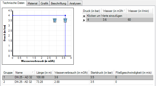
In addition to the graphic, several values can be entered, for example to create a series of measurements for flow rate and flow pressure.

Material
For the application of the contents in the tab Material there are two options.
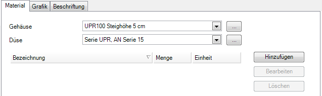
Around Current planning is on the tab Material the current material is displayed. It is not possible to edit the materials here. Further materials can be added, i.e. linked to the selected material. Read more about this in the topic Use materials > Add materials.
The amount of added materials (e.g. number of valves) is in the range calculation changed.
If a graphic is available for the material, this can be done using the button [Graphic] inserted into the drawing.

Around presets materials can be added, which are then always linked to the materials used. Based on the graphic above, this means that the selected valve box (standard box cpl., With screw cap) is always used with the ND 9V valve.
You can also define which materials are to be used in which order. Read more about this in the topic Tips and Tricks > Define material selection.
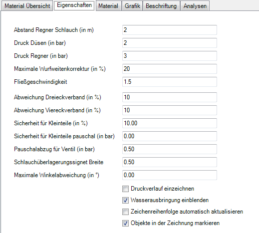
Features
The properties are the input of project-specific data that are necessary for the selection of the sprinkler models and nozzles. The program offers a checklistwhich can be filled out together with the client.
The contents in the tab Features can be distinguished in object properties and material properties. The values given here form the basis for the hydraulic calculations for irrigation planning. The object properties are shown in the upper tree structure of the Current planning or in the presets Are defined.
This information is only informal in nature and has no effect on the actual planning.
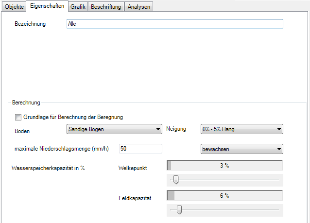
In the area calculation the parameters for determining the need for irrigation are given. These data are decisive for the selection of the sprinklers and for the frequency of watering.
First, you can set whether the area is to be used as a Basis for the calculation of the irrigation should be used. If activated, the parameters for Ground Condition, Tilt and Water storage capacity be determined. It is also set whether the area overgrown (Default) or ungrown is. This results in the maximum amount of precipitation, which can also be edited by hand.
The material properties are defined for the irrigation project to determine the water supply. The default values correspond to the graphic below and should be changed if necessary.
With the option Draw in the pressure curve text information is added to the materials. This is the flow pressure (in bar).
The option Show water application shows, while a valve circuit is being created, the values of the water density in the triangular formation (in mm / h).
For the graphic representation of the irrigation objects, the Update drawing order automatically. Since the update of the drawing order is due to numerous objects can take a long time, this option is disabled by default. The drawing order can, however, be set manually in the menu Extras To run.
With the option Mark objects in the drawing the marked objects in the mass tree are marked in the drawing at the same time (shown with dashed lines). Since this is especially at higher levels or with many objects, delays in working with the Irrigation Manager the option can be deactivated here. This property applies to all objects in the irrigation project. This means that calling up the Irrigation Manager can be significantly accelerated, especially for large drawings.
Graphic
The graphics can be divided into object graphics and material graphics.
You can assign graphics to the objects in the upper tree structure. For more information, see Create graphics im Object manager.
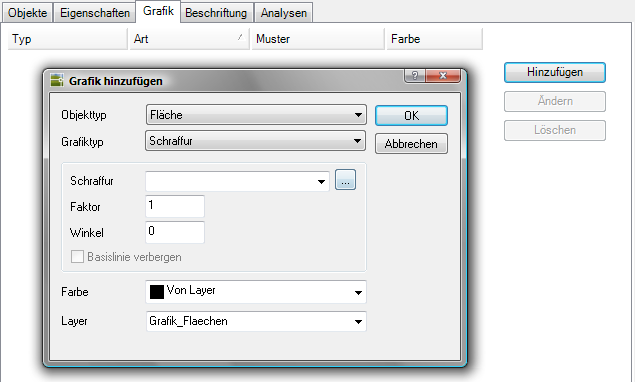
The materials of the irrigation project can be covered with different colors. The definition of the graphic can be carried out on all levels and is then also inherited from subordinate objects. This graphic can also be used in the preferences (see Mass tree > Preferences) for the catalog entry Housing To be defined.

Label
The labeling can be divided into object labeling and material labeling.
You can add labels to the objects in the upper tree structure. You can find more information about this in the section Label im Object manager. In Irrigation Manager the functionality is limited.
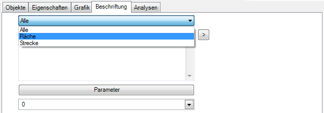
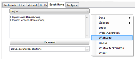
The materials can be labeled with a wide variety of information. This can be done in the Current planning, as well as in the presets happen within the material specifications (see Mass tree > Current planning or presettings). The definition of the labeling can be carried out at all levels and is then passed on to subordinate objects.
Information on the application can be found in the section Use materials > Label materials.
Analysis
You can use this function to check the distribution of the planned sprinklers and use the visual representation in the drawing to determine under- or oversupply. For this purpose, all sprinklers in the current irrigation project are analyzed.
Features
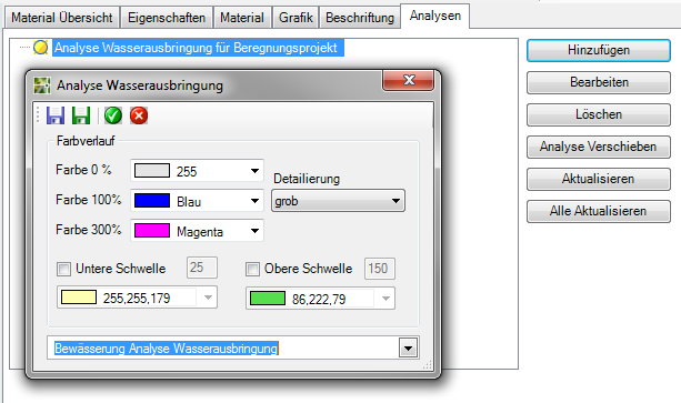
| Add | Opens the dialog Analysis of water application and creates a water analysis. |
| Edit | Opens the selected analysis in the dialog Analysis of water application. |
| Delete | Deletes the selected analysis from the list and in the drawing. |
| Update | Updates the selected analysis with the new sprinkler data. |
| Refresh all | All analyzes are recalculated with changed sprinkler data. |
Functions Dialogue analysis of water application
 | Manage configuration: Opens the dialog for loading, saving and deleting configurations. |
 | save as default: Saves the settings as a configuration Standard so that these settings can be used for new analyzes. |
 | Apply: Closes the dialog and creates a new analysis or applies the settings for the selected analysis. |
 | Abort: Closes the dialog without saving the data. |
| color gradient | Color 0% / color 100% / color 300%: Display of the irrigation density as a color gradient, whereby the individual colors indicate the strength of the water application. Detailing: The color gradient of the water analysis is calculated as a pixel image and inserted into the drawing. The accuracy can be controlled here: rough, medium, fine. The finer an analysis, the greater the memory requirement. This also applies to the number of analyzes in the drawing.
Lower threshold / Upper threshold: Definition of the minimum and maximum irrigation density in%. To display the water output, the areas on which the water output is too low or too high can also be displayed. As soon as the water output reaches these threshold values, the corresponding color is displayed. |
| Layer | Creates the analysis on the selected layer. |

Further information on the application can be found under Check and edit irrigation > Analyze water application.
Sprinkler overview
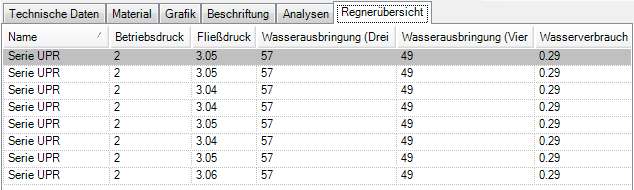
The tab Sprinkler overview lists all sprinklers of the selected valve circuit. To do this, select the level of a valve circuit in the left area of the Irrigation Manager.
Information on operating pressure (in bar), flow pressure (in bar), water output (triangle in mm / h), water output (square in mm / h) and water consumption (in m³ / h) is displayed for each sprinkler.
Pipe dimensions
On the tab Pipe dimensions the materials of the selected water pipe (see Draw line) or the valve circuit (see Draw the valve circuit) listed in a table.

With the help of the pipe dimensioning, you can use the button to create lines and valve circuits while they are being created [Change material] assign different pipe sizes and thus save costs by using smaller DN sizes.
The material change can also be done later using the function  Edit To be defined.
After defining the intersection points for the material change, materials are automatically suggested and the values within the table are recalculated. The material can be selected using the button [...] be changed. Then the manual selection fixed.
As soon as several pipe sizes are used for a line or a valve circuit, the entry in the mass tree changes from the designation of the individual material to "different".