Table of Contents
Create connections
Set water connection
Description
The water connection is the basis for the irrigation system.
With this function, you insert a water connection (symbolized with a picture) in the drawing to determine the position of the water source for the irrigation project. This is done based on the water pressure and volume of the object.
Application
The function can be activated via the menu Connections> water supply> set water connection or via the symbol  be called.
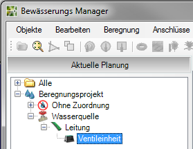
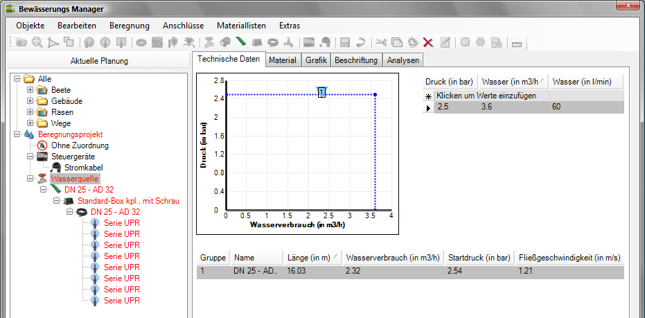
- Select the entry in the left area of the Irrigation Manager Irrigation project and call the command Set water connection .
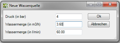
- After the command has been called, the dialog opens New source of water.
- Wear the value for pressure in the space provided.
- Enter the amount of water (either in m³ / h or l / min) for your project.
You can edit these values and add further values for a series of measurements. To do this, mark the entry Water source in the left area of the Irrigation Manager and then select the tab Technical data (please refer Tabs > Technical data).
- Confirm your entry with [OK].
- In the drawing, select the location for the water source.
- The picture for the water connection is inserted into the drawing and the Irrigation Manager opens.
The inserted image can be over the blue Claw to be edited. To do this, the image is marked in the drawing and can then be moved using the middle handle or scaled using the handle on the edge.
Place valve unit
Description
Valves are assembled locally in the valve units, thereby facilitating maintenance of the distributor. With the function Place valve unit, insert a valve unit (symbolized with a picture) in the drawing to determine the position of the valve unit for the irrigation project.
Application
The function can be activated via the menu Connections> set valve unit or the symbol  be called.
- Select the entry in the left area of the Irrigation Manager Irrigation projects and call the command Place valve unit .
- Select the position for the valve unit in the drawing.
- The picture for the valve unit is inserted into the drawing and the Irrigation Manager opens.
The inserted image can be edited using the blue handles. To do this, the image is marked in the drawing and can be moved using the middle handle or scaled using the handle on the frame.
Draw line
Description
If you have placed both a water connection and a valve unit in the drawing, you can now connect these two elements with one another with the help of the water pipe.
Application
The function can be activated via the menu Connections> water pipe> draw pipe or the symbol  be called.
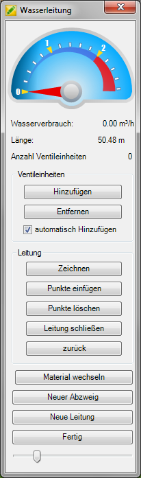
- Select the entry in the left area of the Irrigation Manager Water source and call the command Draw a water pipe .
- Draw a line. Click the picture for the valve assembly.
- Apply the drawn water pipe by clicking the button [Finished] . click
- Im Irrigation Manager the pipe and the valve unit are now sorted below the water source.
You can edit the lines drawn in at a later time by editing the line in the Irrigation Manager mark and then via the symbol  the function Edit . call
Features
| feature | Description |
|---|---|
| Add | As soon as a pipe section is available, valve units can be added to it. To do this, select the valve unit and then the connection point on the water pipe. The selected valve units are then connected to the water source via the pipe (see also add automatically). |
| Remove | Detaches valve units from the water pipe so that these valve units can be added to other water pipes. |
| add automatically | If the valve units are in the vicinity of the drawn water pipe, the objects are automatically connected to the water source via the water pipe. |
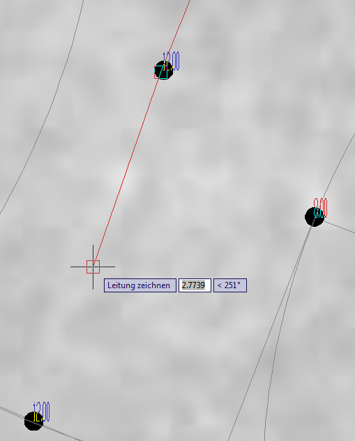
| To draw | Draws a line by specifying points and thus shows the course of the line. |
| Insert points | Inserts points between existing points. To do this, first select the predecessor (point in front of the point to be inserted, in the direction of the drawing) and then the new points. |
| Delete points | Deletes the selected point. |
| Close lines | The water pipe can be closed and thus created as a ring main. To do this, select the point on the line to which the line should be closed. |
| back | Resets the last step in each case. |
| Change material | As soon as a pipe section is available, a change of material, for example to a pipe with a smaller diameter, can be defined. To do this, click on the end point of a pipe section (in the red square). The material change is marked by a line. You can then use To draw Continue. In the Irrigation Manager, the materials of the selected line are displayed in the tab Pipe dimensions displayed. |
| New branch | A new branch is inserted for the current line. To do this, first the connection point on the line is defined and then the new branch (in a different color) is drawn. With End the junction the drawing of the branch is ended and the original course of the current line can be continued. |
| New management | The drawing of the current line is ended (with save) and a new line is started. |
| Ready | Finishes drawing the current line, closes the dialog Water pipe. In dialogue Irrigation Manager the pipe and valve unit are sorted below the water source. |
The material selection of the hoses / pipes for water pipes is done automatically as soon as sprinklers are detected in a valve circuit. However, this depends on the sprinkler data and the material database. The material can also be selected manually (see Use materials > Select material).
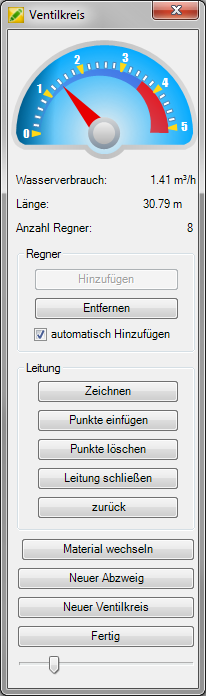
Draw the valve circuit
Description
Create valve circuits and summarize the sprinklers created that have the same requirements on the pressure and generate the same irrigation intensity.
Application
The function can be activated via the menu Connections> Valve circuit> Draw valve circuit or the symbol  be called.
- Select the entry in the left area of the Irrigation Manager Valve unit and call the command Draw a new valve circuit .
- Starting from the valve unit, draw the line to the 1st sprinkler and then on to the other sprinklers in the valve circuit.
- Click the button [Finished]when you want to finish creating the valve circuits.
- Im Irrigation Manager a new object will now be created below the valve unit Valve circuit in which the added sprinklers are automatically sorted.
You can edit the valve circuits at a later time by editing the valve circuit in Irrigation Manager mark and use the symbol the function Edit . call
Functionality
The water consumption for each valve circuit is displayed in the dialog Valve circuit graphically displayed.

The water consumption should not be higher than the amount of water available. If this is foreseeable, create several valve circuits with the New valve circuit button.
As soon as a sprinkler has been selected, the sprinklers are labeled in different colors.
To do this, the value for Dense triangular bond from the tab Technical data used. This value shows the sprinklers in blue that are suitable for combination with the sprinkler already selected in this valve circuit. Unsuitable sprinklers are displayed in red. The display of the water application can be done in the Properties tab (see Tabs > Properties) must be deactivated.
When drawing valve circuits, in addition to the uniform water output, it is also checked whether there is sufficient pressure. Both arise in the Irrigation Manager as follows:
The reason for this can be, for example, that sprinklers with different water outputs were selected or the pressure for the water sources is too low. Therefore check the assumed values.
Further information on this is also available at Tabs > Sprinkler overview.
Features
| feature | Description |
|---|---|
| Add | As soon as a pipe section is available, sprinklers can be added to the valve circuit. To do this, select the sprinkler and then the connection point on the valve circuit. The selected sprinklers are then connected to the valve circuit. (see also add automatically) |
| Remove | Detaches the sprinkler from the valve circuit so that this sprinkler can be added to other valve circuits. |
| add automatically | If the sprinklers are close to the line of the valve circuit, the sprinklers are automatically connected to the valve circuit. Drip tubes and drip tube surfaces are not automatically added to the valve circuit. To do this, select the function [Add] (see above). Then click on the drawn line of the drip tube or the drip tube surface. Then select the connection point on the valve circuit. |
| To draw | Draws a line by specifying points and thus shows the course of the line. |
| Insert points | Inserts points between existing points. To do this, first select the predecessor (point in front of the point to be inserted, in the direction of the drawing) and then the new points. |
| Delete points | Deletes the selected point. |
| Close line | The valve circuit can be closed and thus created as a ring line. To do this, select the point on the line to which the line should be closed. The pressure within the ring main is calculated in such a way that there is less pressure loss at the end of the line. |
| back | Resets the last step in each case. |
| Change material | As soon as a section for a valve circuit is available, a material change, for example to a pipe with a smaller diameter, can be defined. To do this, click on the end point of a section (in the red square). The material change is marked by a line. You can then use To draw Continue. In the Irrigation Manager, the materials of the selected valve circuit are displayed in the tab Pipe dimensions displayed. |
| New branch | A new branch is inserted for the current valve circuit. To do this, first the connection point on the line is defined and then the new branch (in a different color) is drawn. With End the junction the drawing of the branch is ended and the original course of the current valve circuit can be continued. |
| New valve circuit | The drawing of the current valve circuit is ended (with save) and a new valve circuit is started. |
| Ready | Ends the drawing of the current valve circuit, closes the dialog Valve circuit. In dialogue Irrigation Manager a new valve circuit object is created in which the added sprinklers are sorted. Each valve circuit contains the connected sprinklers. |
The material selection of the hoses / pipes is done automatically for valve circuits, provided that the sprinkler data and material database allow this. The material can also be selected manually (see Use materials > Select material).
Set control unit
Description
Control devices automate the operation of an irrigation system and thus increase the benefit factor of the system many times over.
With this function, you insert a control unit (symbolized with a picture) in the drawing to determine the position of the control unit for the irrigation project.
Application
The function can be activated via the menu Connections> set control device or the symbol  be called.
- Select the entry in the left area of the Irrigation Manager Irrigation project and call the command Set control unit .
- Select the position for the control unit in the drawing.
- The picture for the control unit is inserted into the drawing and the Irrigation Manager opens.
The inserted image can be edited using the blue handles. To do this, the image is marked in the drawing and can be moved using the middle handle or scaled using the handle on the frame.
In the left area of the Irrigation Manager, the entry ECUs marked, you can draw one or more cables (in the next chapter) to ensure the power supply.
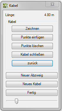
Draw cables
Description
As soon as you have placed a control unit in the drawing, you can use this function to create a linear connection from the control unit to the power supply.
Application
The function can be activated via the menu Connections> Power Cable> Draw Cable or via the symbol  be called.
- Select the entry in the left area of the Irrigation Manager Controller and call the command Draw power cables .
- Starting from the control unit, draw a line to show the course of the line.
- Click the button [Finished]if you want to create the creation of the power cable.
- Im Irrigation Manager is then the power cable below the entry ECUs sorted.
You can edit the drawn power cable at a later time by removing the power cable in the Irrigation Manager mark and use the symbol the function Edit . call
| feature | Description |
|---|---|
| To draw | Draws a line by specifying points and thus shows the course of the line. |
| Insert points | Inserts points between existing points. To do this, first select the predecessor (point in front of the point to be inserted, in the direction of the drawing) and then the new points. |
| Delete points | Deletes the selected point. |
| Close the cable | To close the cable, select the point in the drawing to which the line should be closed. |
| back | Resets the last step in each case. |
| New branch | A new branch is inserted for the current line. To do this, first the connection point on the line is defined and then the new branch (in a different color) is drawn. With End the junction the drawing of the branch is ended and the original course of the current line can be continued. |
| New cable | The drawing of the current line is ended (with save) and a new line is started. |
| Ready | Finishes drawing the current line, closes the dialog Cables. In dialogue Irrigation Manager the cable is sorted below the control unit. |