Table of Contents
SmartDGM in BIMXPERT
Command: SMARTDGM
Description
The SmartDGM is the digital terrain model for BIMXPERT. All functions for digital terrain processing are in the window Smart DTM made available. Means Surface, profiles, volumes or sets of edges a terrain model can be mapped and used quickly and easily in CAD.
As the basis for a Surface do you need Lines, polylines, 3D polylines, circles or arcsyou as Breaklines or Boundary edge define. over Edge sets add edges to the DTM later.
With a Profile you can use a profile line to show the course of the terrain clearly with height information in the drawing. Let yourself Volume Calculate in order to be able to estimate quickly, for example, the order or contract for a construction project.
Information on the individual functions in the Smart DTM can be found in the following topics:
Terrain Model Objects
All of DATAflor CAD generated DTM data (objects) are saved in the drawing and not in separate configuration files. This simplifies data backup and the creation of safety copies, since the drawing only has to be copied.
All objects are dependent on one another. This means that if, for example, the position of an edge is changed, all DTM objects derived from it are automatically updated and recalculated.
Via the main page of the window Smart DTM you have access to the different areas to create the terrain model objects.
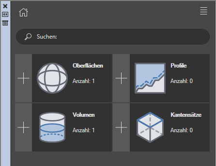
Depending on which area of the Smart-DTM you are in, different options are available. The functions are described in the individual chapters:
| Surfaces |  | To add a surface, you need the basics in the drawing as lines, polylines, 3D polylines, circles, or arcs. Read more under Surfaces. |
| Profile |  | With the help of a profile, you can quickly display the cross-section, including additions and removals, at any point on a surface. Read more under Profile. |
| Volume |  | With the help of this function it is possible to have the volume calculated for an excavation, for example. You either need two surfaces where you choose a base and a target surface. Alternatively, you can use the horizon enter an altitude value. Read more under Volume. |
| Edge sets |  | Combine lines, polylines, circles and arcs in break lines or boundary lines and assign these to new or existing surfaces. Read more under Edge sets. |
A name must be assigned to the object for each terrain model object. Assigning unique names helps when editing the objects later.
Configuration
In the configuration of the Smart-DTM, the display of the terrain model objects, e.g. in relation to Colors, layers and dimensions, and change this into Templates save. You can then freely assign these templates to the individual terrain model objects.
You can access the configuration via the Tool icon top right in the Smart-DTM.

The configuration can also be opened if you have already selected a certain terrain model object. There click on the tool symbol. In this case, only the options relevant to the selected terrain model object are displayed.

In the configuration is the DATAflor Standard (cannot be changed). You can use this to own templates about the Plus symbol define. All configurations are then available for selection in the list and can also be checked here Set as standard.

Options
Enter your individual settings: You can change the colors by clicking on one of the color buttons. A color palette opens where you can select an individual color.
| contour lines |  | You can the Intervals between the contour lines set and differentiate between main and sub-contour. The main contour is usually the larger interval, the sub-contour determines the smaller intermediate steps of the contour lines. It is possible to assign different colors. |
| Profile |  | With the profiles you can define which Colors the frame of the Profile as a whole, the profile lines and application and removal to have. You can Layer on which the profiles will be drawn. |
| Measures |  | You determine the measurements which measures are displayed for the profiles should be and in which Text size, Also the Title can be shown or hidden in the profiles or the text size can be changed. To change the text size, enter the desired values in the appropriate field. |
The configuration files are stored in the user directory of DATAflor CAD saved.