Table of Contents
Point set
Description
A point set is a collection of elevation points. It forms the basis for calculating surfaces.
With the command Digitize individual height points are generated, which are then generated with the command Combine height points to a point set can be combined to form a point set. Even when using the commands Import point file, Derive drawing elements and Digitize points from texts a point set is created.
Application
Create point set
Quick DGM> right mouse button on the group Terrain> Point Set> From File (please refer Import point file)
Quick DGM> right mouse button on the group Terrain> Point Set> Derive From Objects (please refer Derive drawing elements)
Quick DGM> right mouse button on the group Terrain> Point Set> Digitize (please refer Digitize)
Quick DGM> right mouse button on the group Terrain> Point Set> from Point Cloud (please refer Point set from punk cloud)
Quick DGM> right mouse button on the group Terrain> Point Set> Digitize Points from Texts (please refer Digitize points from texts)
Edit point set
If you are the Info (please refer Quick-DTM (AutoCAD based) > Functions in the toolbar) for the point set can be opened on the tab Overview change the point set.
The fields within the table can be edited so that the individual values can be changed or re-entered. At the same time, the selected point or points in the drawing are marked with a cross. If the column header (e.g. description) is dragged into the line above, the points are sorted into groups.
![]()
If one or more points are marked in the table, the following functions can be called with the right mouse button:
| Renumber | A variable starting value for the point set can be entered here. Following will be Points of the point set renumbered. |
| Move points | To adjust the position of elevation points in a point set, the command Move elevation points called. |
| Delete | The selected points are deleted from the point set. |
| Zoom | In the drawing, the selected points are zoomed in. |
| Copy to new selection set | The selected points are marked for editing in the drawing, for example to copy them. |
| Copy to existing selection set | The selected points are added to an existing selection. |
| Create 3D polyline from point list | A 3D polyline is created that connects the points in the order in which they are selected. |
If you click in the last (empty) table row, a new point with a consecutive number is created.
To delete points, highlight the points and press Del-Button. Confirm the deletion of the point selection with [Yes].
Further editing options for points in point sets:
| Add points | To add points to a point set, existing elevation points in the point set can be copied using the COPY command. The new (copied) point then automatically becomes part of the point set. You can also add a point file, points from objects, and digitized points (see Add elevation points). |
| Delete points | The DELETE command can be used to remove points from a point set. The deleted point is then automatically removed from the point set and the terrain model objects are updated if necessary. |
| Change points | The position of height points in a set of points can be changed with the MOVE command or alternatively by selecting with the mouse and moving with the handle (pick point). The command is also available for moving single or multiple points Move elevation points is available for storage, management and analysis. |
When moving over the pick points, height points behave in the same way as blocks with attributes. To the High point (a.) to change, this has to be done with the mouse marked become (b.). The Point description from the location changed (c.), by moving the handle in the middle, the High point postponed (d.), with the text being carried along.
 a. |  b. |
 c. |  d. |
Editing of points should only be done in the top view and not in an isometric view.
Features
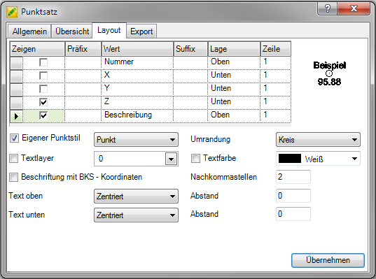
Layout tab
On the tab layout the representation of the points (e.g. number of decimal places) can be changed later. Point size and point symbol can be changed using the button [Point style] to adjust. The dialog for this can also be opened with the command PYP be called.
Will the option Own point style activated, individual settings for displaying the point and the border can be set. The point size settings are still adopted by the point style.
The Definition of the point style should be on absolute Values can be set so that the size of the points is independent of the representation of the drawing on the screen. If the values are proportional to the screen, the size is recalculated each time the zoom factor is changed. This can have undesirable effects, for example when outputting a plan.
If the setting in the Template file the change of the point style does not have to be adjusted for each drawing.
For the layout can also Text layer and Text color to be selected. If these two options are not activated, the layer and color of the points are automatically used, which are on the tab General were established.
The point labeling is controlled in the table. In the column Show the individual labels are switched on or off. The column for the location controls whether the label should be displayed above or below the point symbol. In the column row the line number (1,2, 3 or XNUMX) can be selected for the labeling. If several texts are assigned to the same line, they are displayed next to one another.
The settings on the tabs General and layout can in the window Configuration (please refer Quick-DTM (AutoCAD based)) can be defined as a default for all further drawings.
Derivatives tab
On the tab Derivatives can change the settings for the dynamic derived geometries can be checked and changed.
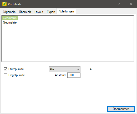
The derived geometries are displayed in the upper area. If a geometry is marked, it will also be marked in the drawing. With a click with the right mouse button on a geometire you can zoom in on it. The geometry can also be deleted.
The geometry options selected during the derivation are displayed in the lower area. These can be adjusted if necessary.