Table of Contents
Special modeling
Description
Many terrain cultivation tasks can often only be implemented in several steps with modeling and several edge definitions. The special modeling within the window Quick-DTM (AutoCAD based) combine these different work steps into a single one and create the modeling fully automatically.
Landfill / pit
Description
With this function, a landfill or a pit can be defined by specifying the subgrade height or a reference surface, which is then meshed into the terrain with constrained edges.
This can be used, for example, for a construction pit (subgrade below the terrain surface) or a landfill (subgrade above the terrain).
Prerequisites are an existing boundary (e.g. embankment base for landfills) and at least one triangulation.
Application
- Mark the desired triangulation (reference surface) in the DTM tree and call it with the right mouse button Tools> Special Modeling> Landfill / Pit .
- You are now prompted to choose the outer boundary (closed polyline). The polyline does not have to be lifted onto the terrain beforehand. This is done automatically by the function.
- The following configuration dialog then opens:

Enter the in the upper area designation for modeling.
You can also determine whether a fixed installation height or a reference to a different terrain surface is to be used. When using a fixed Installation height the subgrade of the pit is level and on the same level. Will be a Reference surface used, the subgrade of the excavation corresponds to the surface situation of the reference surface.
In the area embankment the information for the course of the slope is entered. - When confirming with [OK] the modeling is inserted into the surface.
Use Cases
Bounded terrain (blue line)
Thick with lower edge of the slope 28 m - level subgrade

disposal site with an upper edge of the embankment 40 m - level subgrade

Thick with reference surface - subgrade from reference site

Platform system
Description
With the double edge, single or multiple steps / plateaus can be modeled in a terrain (e.g. a place with surrounding stairs or ramps). One or more closed polylines are required, which must be raised to the correct installation heights in advance.
Application
- Select the desired triangulation in the DTM tree and call it with the right mouse button Tools> Special modeling> Platform system .
- The following configuration dialog then opens:
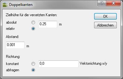
The Target height for the offset edges indicates the height of the new edges, e.g. for steps this would be the slope per step.
The distance specifies the offset of the new edges. The default is 0.001 (= 1 mm). This is necessary because edges cannot be congruent on top of each other.
The Direction it can be set whether a manual specification of the direction should be carried out for each edge (= query). Alternatively, constant can be set, whereby a vector direction must be specified here, which is then used as the default setting for all edges. Example: 0, -1 means downwards (X = 0; Y = -1). - When confirming with [OK] the dialog is closed and the corresponding polylines must be selected in the drawing. When all edges are selected, right-click or Enter the acquisition will be completed and the modeling will be generated.
Use Cases
Terrain with boundaries (blue lines)

Place with stairs

Congruent breaklines (walls)
Description
With this type of modeling, the following task can be solved: Within a site there are several adjacent areas with different heights that are to be created as breaklines.
Application
- Sort the boundary edges at the correct height in the terrain.
- Mark the desired triangulation in the Quick-DTM and call it with the right mouse button Tools> Special Modeling> Coincident Breaklines (Walls) .
- In the drawing, select the breaklines you want.
- When all edges are selected, right-click or Enter the acquisition will be completed. The dialog for the edge definition then opens. Confirm this with [OK].
- The new modeling is automatically inserted into the triangulation.
Use Cases
Terrain with adjacent areas (blue lines)

Terrain with contiguous break lines (e.g. house cellar)

Terrain with connected breaklines (e.g. wall)
Uniform application or removal
Description
This function creates a uniform application or removal, specifying a parallel shift, which is then meshed into the terrain with a constrained edge or break edge. This can be used, for example, for building layers (road construction). Prerequisites are an existing boundary (closed polyline) and at least one triangulation.
Application
- Mark the desired triangulation (reference surface) in the DTM tree and call it with the right mouse button Tools> Special modeling> Uniform application or removal .
- You will now be asked to choose the outer boundary. The polyline does not have to be lifted onto the terrain beforehand. This is done automatically by the function.
- The following configuration dialog then opens:
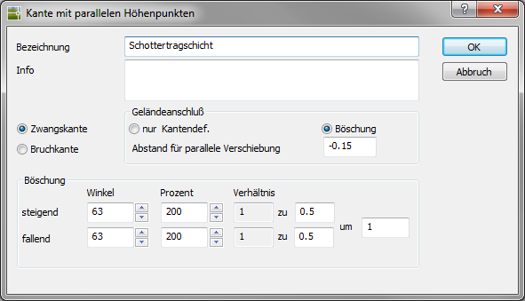
At the top is the input of the designation for modeling.
Select the type of edge in the middle area Forced edge or Breakline.
Give one Distance for parallel displacement at. The distance can be negative as well as positive. The edge type forced edge enables the use of an embankment in the area connection.
In the area embankment the information for the course of the slope is entered - When confirming with [OK] the modeling is inserted into the surface.
Use Cases
Bounded terrain (blue line)

Terrain with even removal
