Table of Contents
Layout plan
Description
For a layout plan, point blocks with various information about the terrain are inserted into the drawing at regular intervals.
Before using the function, a closed boundary line (polyline, rectangle, etc.) must be drawn that defines the area in which the layout plan is to be created. Optionally, a gradient can also be drawn in to which the blocks are to be aligned.
Application
- Mark the desired surface (triangulation or grid) in the Quick-DTM and call it with the right mouse button More tools> Layout plan on. The following configuration dialog opens:
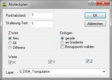
- The Point spacing and Scaling text the distances for the grid and the block size can be specified.
In the area Values X, Y and Z coordinates can be activated, whereby three different information can be used for the Z value (area Z-Value).
In the area Insert the grid can also be aligned orthogonally on a gradient. The normal reference to the origin of the drawing can be changed by selecting a different reference point.
The default layer is the current one Layer. However, a new layer can also be entered, which will then be generated automatically. - When confirming with OK the queries are made depending on the selected insertion option (boundary line, gradient, reference point). After selection, the layout plan is generated in the drawing
The block that is used for the inserted point symbols is in the file LPAPLN $$. DWG in the user directory of DATAflor CAD filed. The spacing and text sizes of the attributes can be changed in this file. These changes are automatically applied in new drawings. In old drawings, the update is done by redefining the LPAPLN $$ block via the external file.