Table of Contents
Landscape object
Command: DFLSO
Description
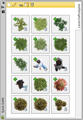
With the function Landscape object you can use dynamic drawing objects from the window Quick graphics use or create and manage there. These objects rotate with the viewer and thus adapt automatically when changing from top view to view, for example.
Application
- If you want to insert a landscape object, click with the left mouse button on a symbol within the palette and keep the mouse button pressed.
- Drag the mouse pointer to the drawing area and release the mouse button.
- Pick the first insertion point.
- Drag the pointer diagonally. Click with the left mouse button when the desired size is visible or enter the desired size using the keyboard.
- Insert further objects into the drawing by clicking the respective insertion point in the drawing.
- End the insertion of objects with the key Enter.
Library elements with a lock shown at the lower right corner of the preview image are encrypted and protected elements. These elements can be used without DATAflor CAD not Show.
The window Quick graphics can you like the window Features Position / fix in the work area.
Features
 | Create new object: Opens the dialog Landscape objectsto create a new landscape object. |
 | Edit: Opens the dialog Landscape objectsto edit the selected landscape object. |
 | Show text: Displays the symbols with or without text. |
 | Image size: Displays small or large icons. |
 | different: Inserts the selected object multiple times or individually into the drawing. |
Additional functions are available for the individual landscape objects. If you right-click an icon, you can view the object Delete, Renamewhich Update tool image (Icon is updated automatically) and another one Specify picture (select the desired image for the symbol).
In the Features of the symbol there are object-specific parameters that are set in the dialog Landscape objects have been defined.
Create a new landscape object
- You have two options for changing the appearance of the objects for the 3D view and for the 2D supervision set.
- Select in the dialog Landscape Features> Properties tab for picture, picture (2D) or block the function
 to open your own graphics.
 - Also open the Quick manager. Click with the left mouse button on an image or block within the palette and keep the mouse button pressed. Drag the mouse pointer in the dialog Landscape Features> Properties tab on one of the squares below picture, picture (2D) or block and release the mouse button. The object is inserted.
- If necessary, repeat the steps for all views.
- Once you make the selection with [OK] confirm, the landscape object is created in the palette. In the window Quick graphics the preview image with a symbol in the top left
 provided.
Assign plants and material
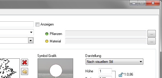
It is possible to assign a plant and / or a material to the landscape object, for example to output a plant or material list via the object manager.
If the object is inserted into a drawing, an entry is automatically made in the Object manager created. This entry contains the number of objects inserted.
So you can drag and drop it out of the window Quick graphics create a material or plant plan.
- Click in the dialog Landscape Features> Properties tab on the button [...].
- The material or plant editor opens.
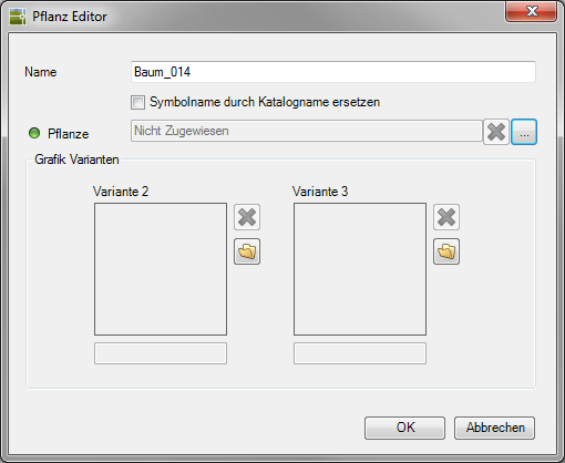
- In the dialog you can assign a new name for the object or replace the name with the catalog name of the material / plant.
Click the button [...]to select a material / plant from the installed material / plant catalogs and assign it to the object.
Instruct the plants Quality to, this is used automatically when inserting. If no quality has been selected, you will be asked which quality should be used when inserting the plant.
You can also assign graphic variants 2 and 3. These are automatically saved in Object manager entered as graphic variants.
- Confirm your entries with [OK].
The preview image in Quick manager is now provided with a symbol at the top right. This symbol shows you whether a material  , a plant
  or material and plant
  assigned to the object.
Define the representation in the drawing
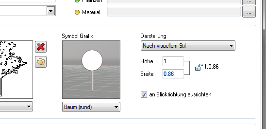
Select in the dialog Landscape Features> Properties tab > Area presentation select the style from the list of how the landscape object is to be displayed in the drawing: as Symbol, Block, BILD or According to visual style. Will the choice According to visual style is hit with the visual style Realistic or when rendering the image displayed. With visual styles like 2D wireframe or Wire body the block is used.
Is no block is present, the BILD displayed.
When inserting and moving objects in the drawing, the selected Icon graphic .
The option align to viewing direction has the effect that the object is always facing the viewer, regardless of the selected view.
Advanced Graphics Settings tab
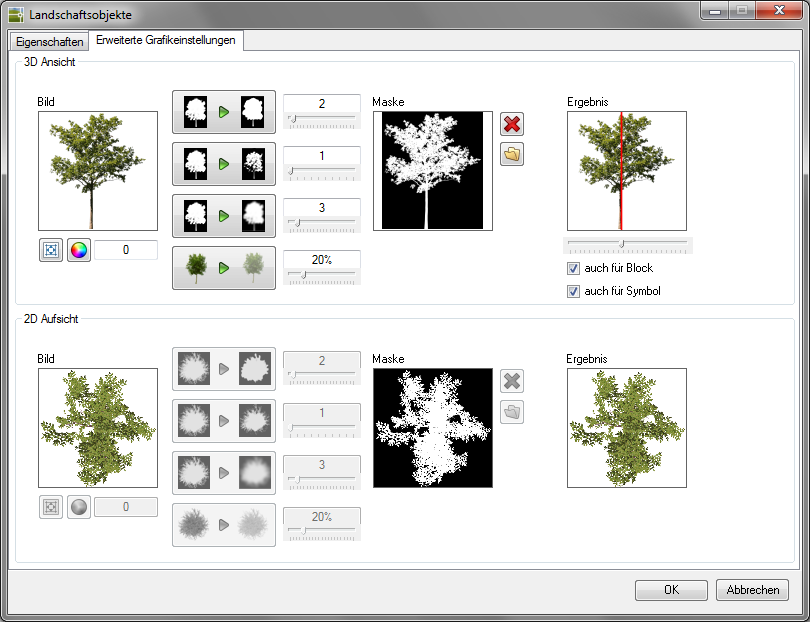
 | Crop the image to the visible area: Edge areas "without information" are cut off. |
 | Switch color to transparent: opens the picture. As soon as you click, transparency will be applied to that color. Im input box on the right the tolerance of the color transparency can be controlled. The higher the value, the larger the color range that is set transparent. |
 | Apply median to mask: smaller marginal areas are combined to form larger ones. The slider controls the intensity. |
 | Shrink the non-transparent area: the transparent area is enlarged at the edge areas. The slider controls the intensity. |
 | Blur mask: the contrast at the transition from the mask to the transparent area is reduced, the image remains sharp. The slider controls the intensity. |
 | Transparency of the visible areas: Object is set transparent with a specified percentage. The slider controls the intensity. |
| Mask | Displays the mask with the current settings. An image with image transparency (e.g. PNG) automatically shows the mask. For an image without image transparency (e.g. JPG) the transparency must be created. |
| Load a mask whose dimensions correspond to those of the image. |
| Result | Displays the image with the current settings. |
 | Determine the axis of rotation: Specify the center of rotation of the image. |